
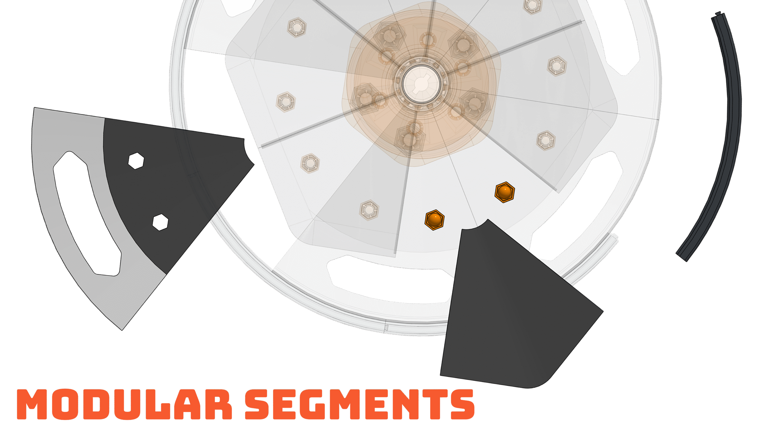
As the covers are 3D printed, and are modular, a failed print only ruins one segment instead of the entire wheel cover. With each piece being independent, a bad layer, warping, or bed adhesion failure stays isolated. Keeping material waste and reprint time low when producing a full set.

Damaged or curb-rashed segments can be removed and replaced individually without tools or taking the rest of the cover apart. The user only needs to replaces what is actually broken. Turning what would normally be a full product failure, into a simple part swap.

Damaged or curb-rashed segments can be removed and replaced individually without tools or taking the rest of the cover apart. The user only needs to replaces what is actually broken. Turning what would normally be a full product failure, into a simple part swap.
Each segment locks to its neighbors and to the center hub. The geometry maintains engagement under centrifugal force, road vibration, and thermal expansion and contraction. The assembly stays secure even when individual segments are missing or damaged.

Due to the segmented design, parts can be printed in different colors or materials and still lock together on the same wheel. This allows intentional color blocking or gradual replacement of worn pieces without forcing a uniform look across the full set.
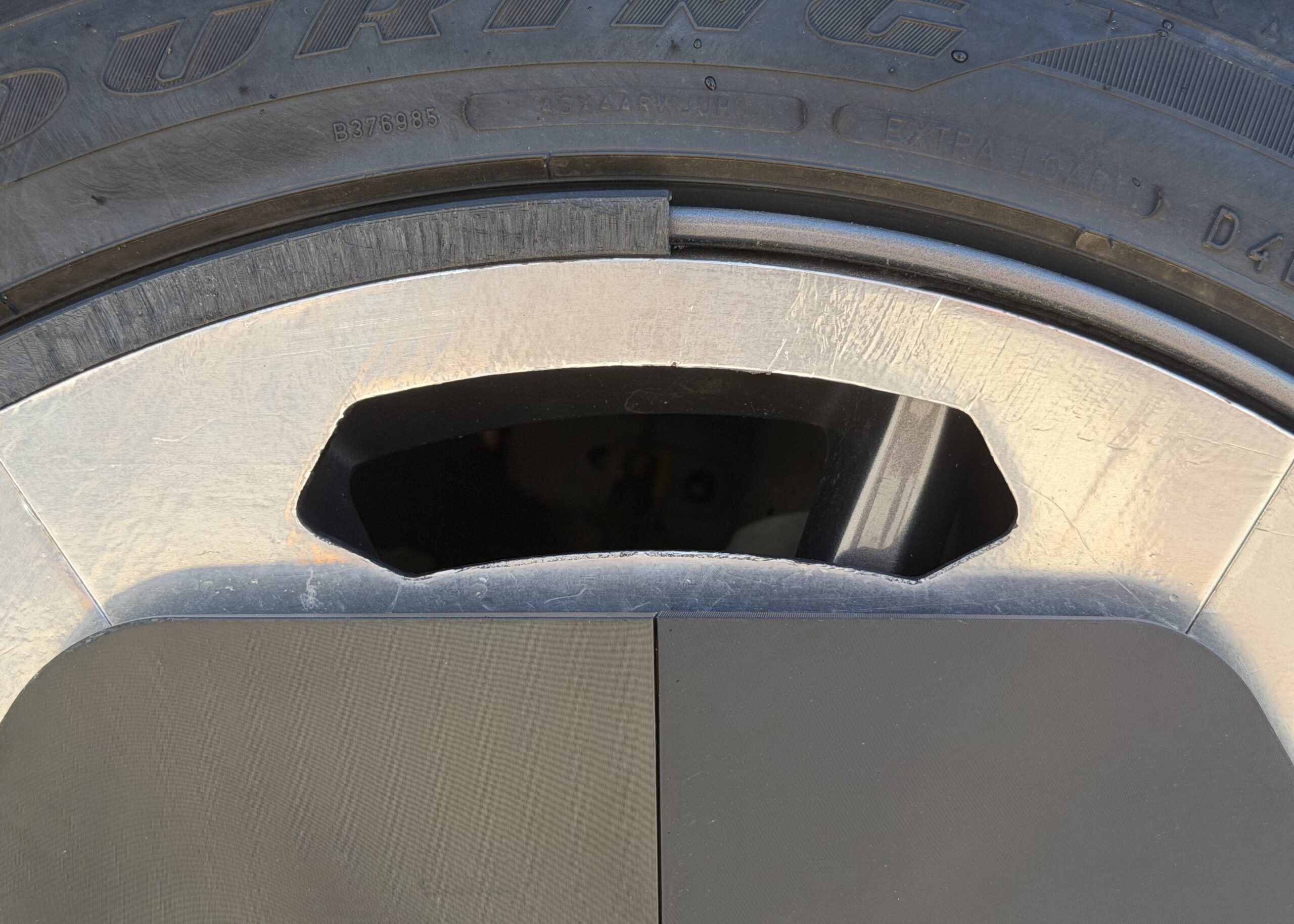
Due to the segmented design, parts can be printed in different colors or materials and still lock together on the same wheel. This allows intentional color blocking or gradual replacement of worn pieces without forcing a uniform look across the full set.
If a specific part fails or needs improvement, only that segment has to be replaced. For example, when the middle hexagon walls proved too thin and broke during reinstall, the thicker-walled revision could be swapped in without reprinting or discarding the rest of the cover.

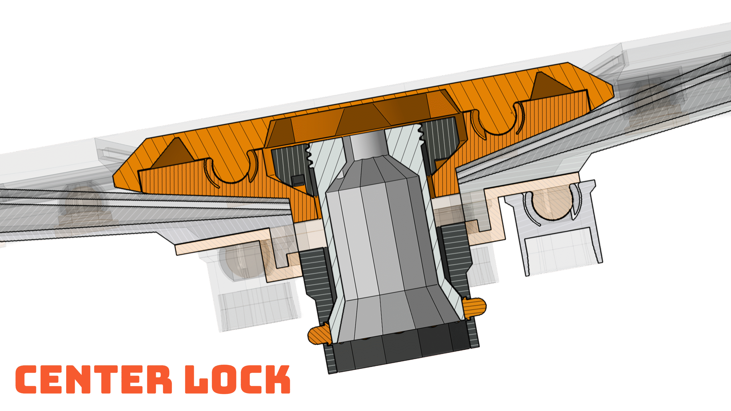
The center assembly passes through the cover and into the original wheel hub. Small nubs expand outward when the center section is pulled, creating a positive mechanical lock against the OEM geometry. This gives the clamping nut a rigid base instead of relying only on friction or surface contact.

The nut both clamps the full cover stack to the wheel and uses a non-standard drive geometry. It sits flush with the surrounding surface, leaving no room for fingers. Removal requires a matching 3D-printable tool, raising the effort needed for casual tampering while remaining fully serviceable by the owner.

The nut both clamps the full cover stack to the wheel and uses a non-standard drive geometry. It sits flush with the surrounding surface, leaving no room for fingers. Removal requires a matching 3D-printable tool, raising the effort needed for casual tampering while remaining fully serviceable by the owner.
Early versions of the bolt used insufficient wall thickness around the threads. Repeated install and removal cycles caused the layer lines to break and separate, creating a risk of the bolt failing while the car was moving. The solution, increasing the radial wall thickness around the threaded section eliminated the failure mode. The revised geometry has held through continued high-mileage use with no further issues.

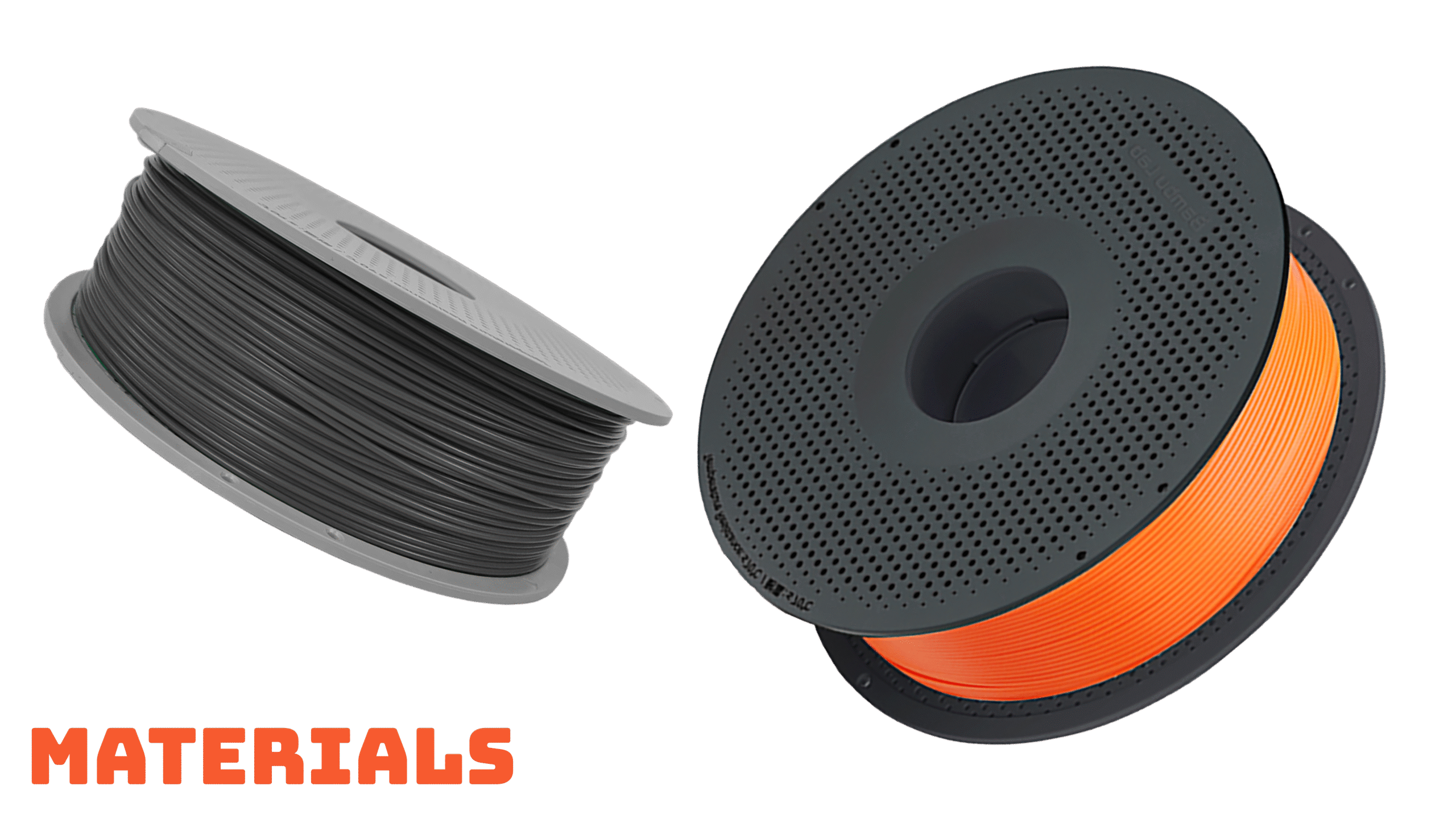
Used for the large outer segments. PETG-CF prints more reliably at this size than ABS, with lower warping and better bed adhesion on big parts. It also provides the necessary heat resistance for both ambient temperature swings and proximity to the brakes while remaining tough enough for impact.
Used for the center hex, locking components, and clips. ABS was chosen where higher strength and better long-term heat resistance mattered more than print ease. These smaller parts can be printed more controlled, so the warping risk of ABS was acceptable in exchange for the mechanical properties.
Used for the center hex, locking components, and clips. ABS was chosen where higher strength and better long-term heat resistance mattered more than print ease. These smaller parts can be printed more controlled, so the warping risk of ABS was acceptable in exchange for the mechanical properties.
The combination has held up through more than 10,000 miles of mixed weather, including snow, rain, and high heat.
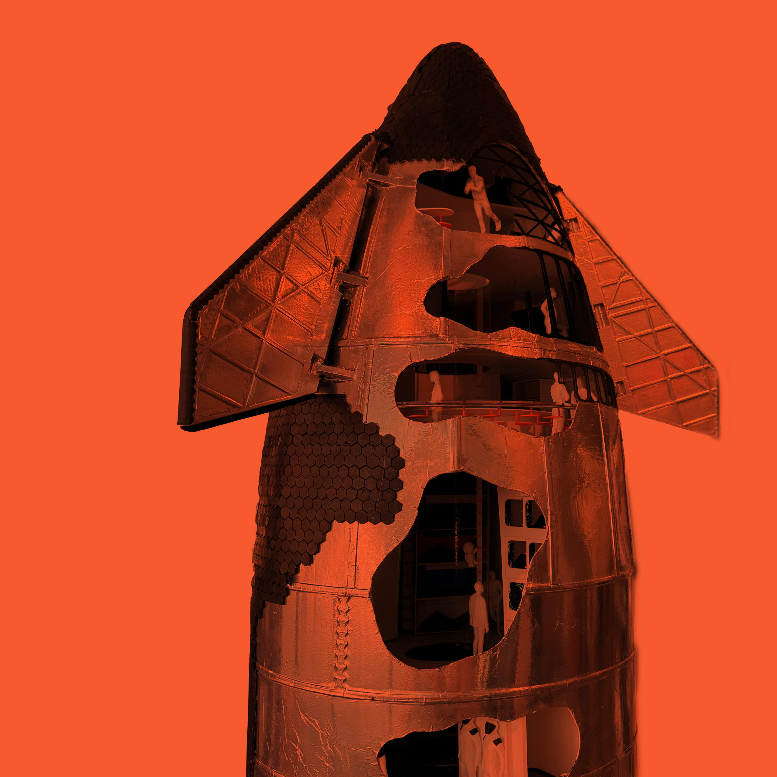
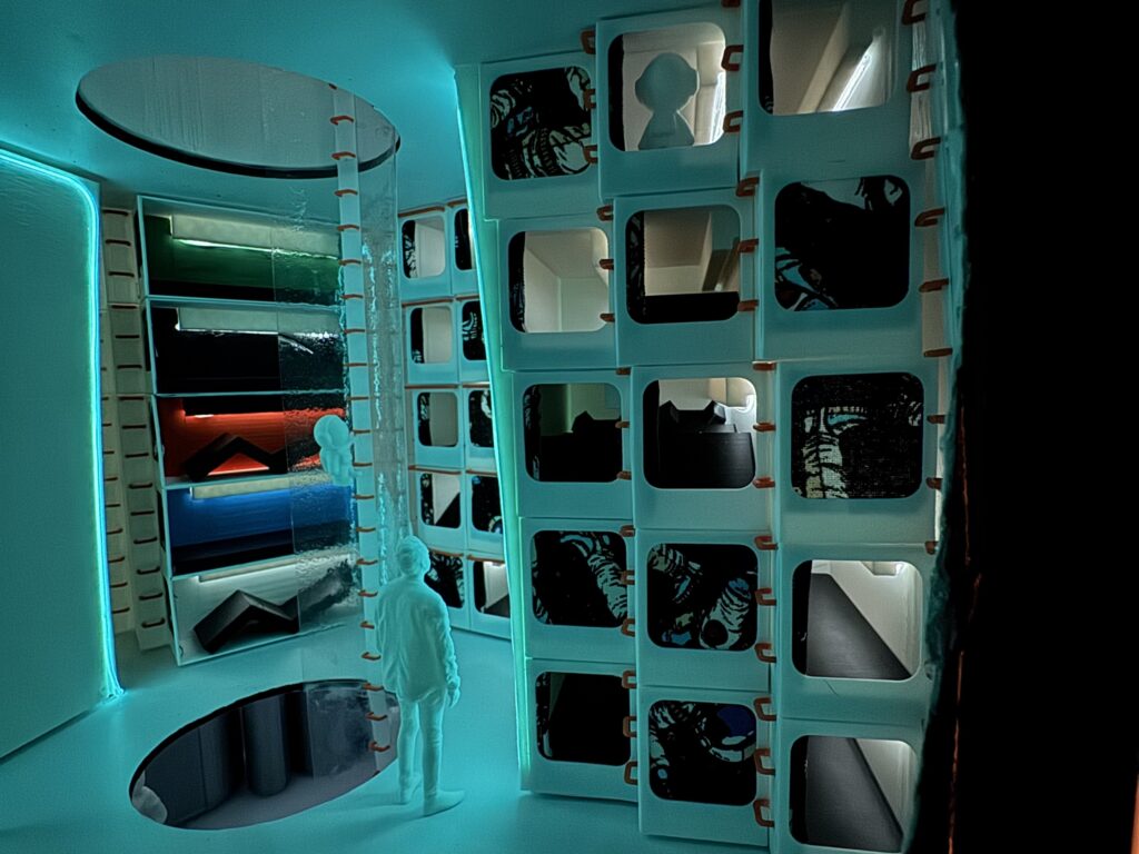
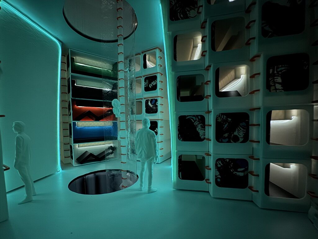
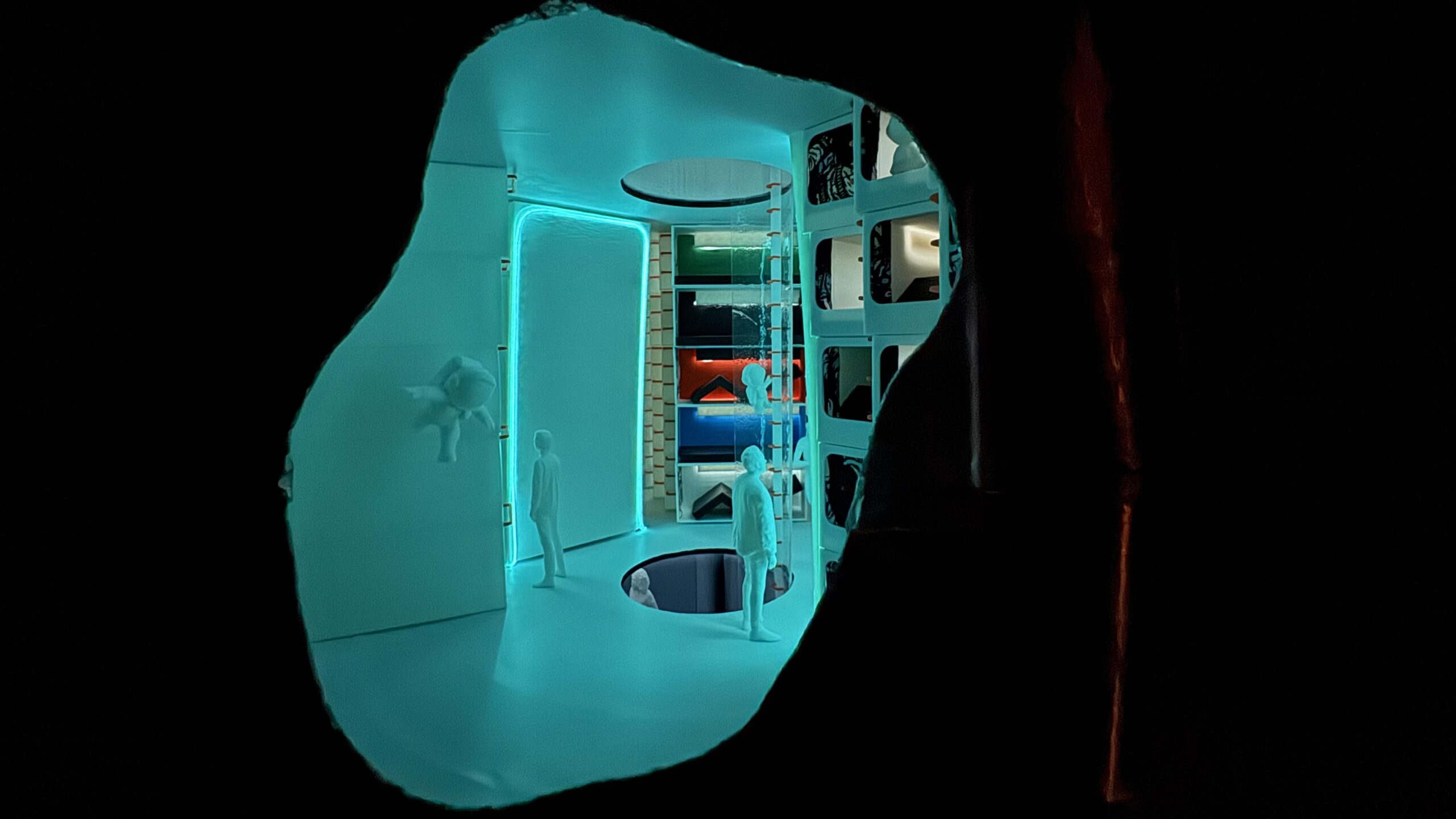
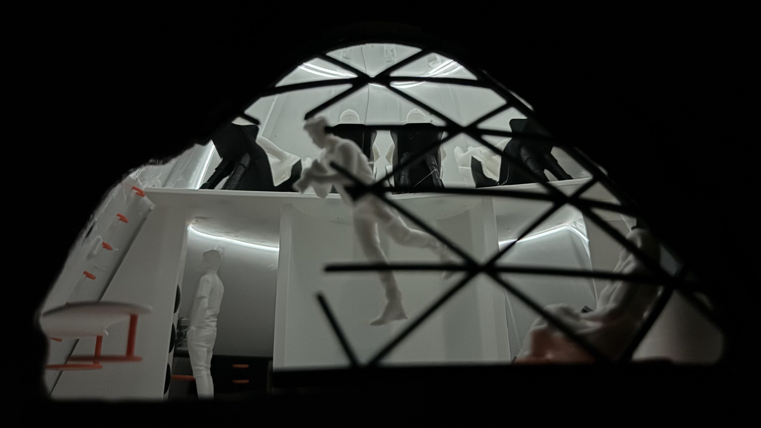
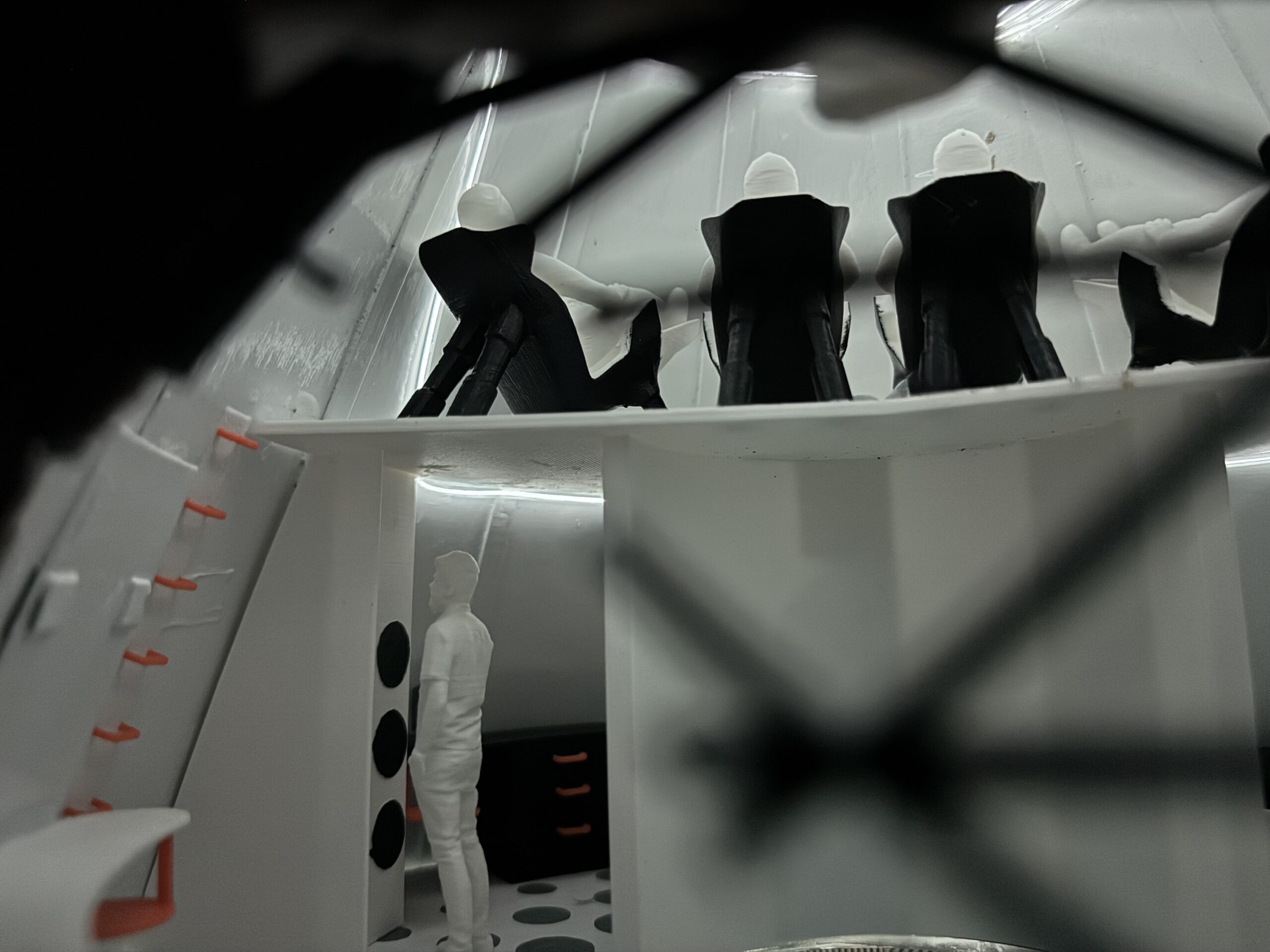
One hundred pods. One person each. A three-shift, 34-pod version was on the table and got dropped as on a Mars-length trip people need a place that is theirs, and a pod they can make theirs.
The deck stays dark so when you’re in the room you wind down. Each bunk has its own under-cabinet light. A blackout curtain seals the cell.
The mattress converts to a launch/landing seat. It is a worked-out idea, not a flight-qualified mechanism, the goal was to not have to carry 100 beds and 100 seats. Dual-wall structure on the level holds water between the skins: drinking supply and a radiation shelter in the same volume.
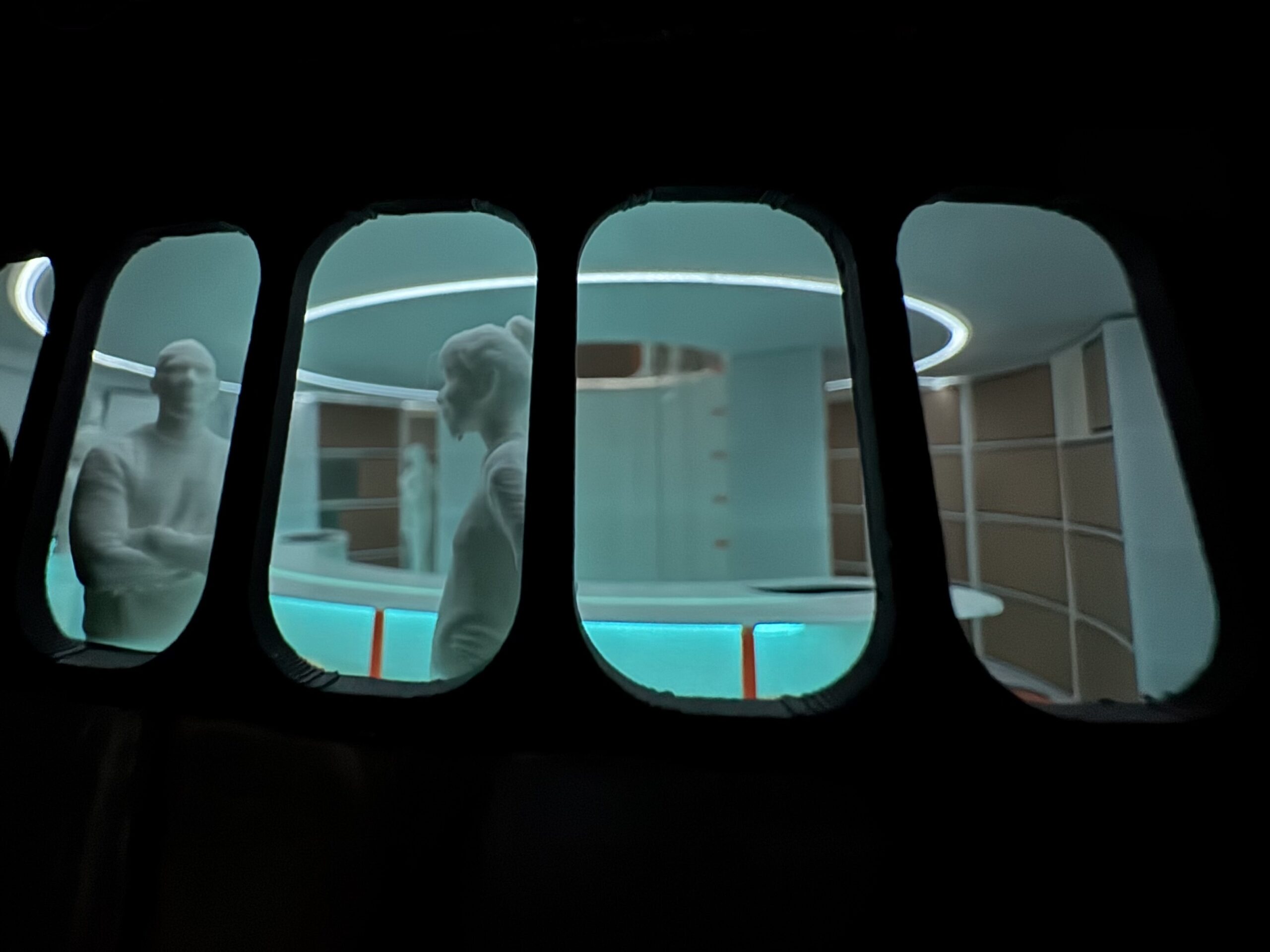
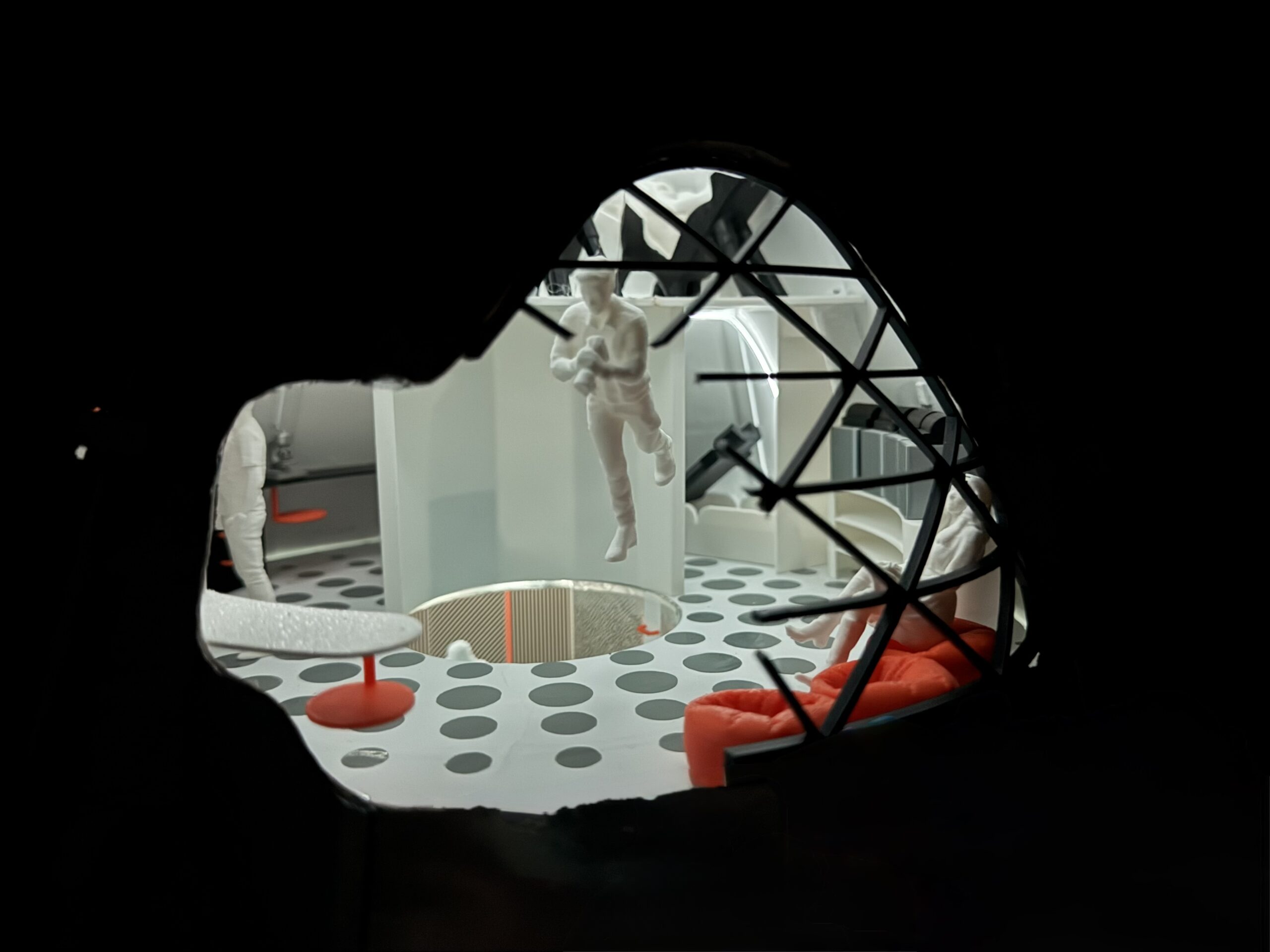
A central island is the cooktop and the table. Twenty-five seats attached to the counters can swivel in 0g and 1g, so the room faces itself instead of a wall.
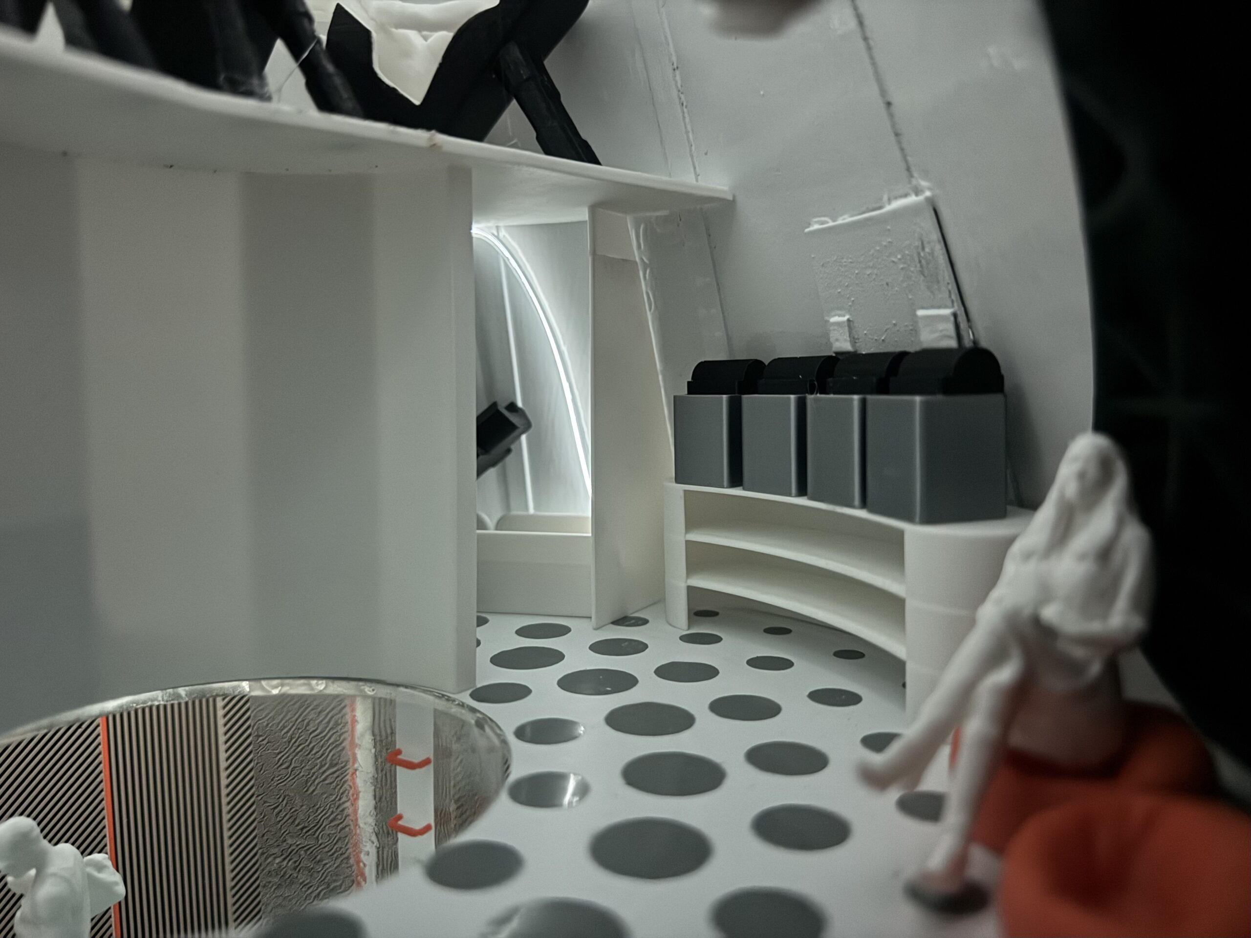
Cooking is magnetic induction. Pans locate on the rings and the heat stays in the cookware. A sink and fill stations handle water and dishes. Dry stores sit in the back side of the ship, with more in storage and utilities. One hundred people eat in shifts. This deck is sized for that, on purpose.

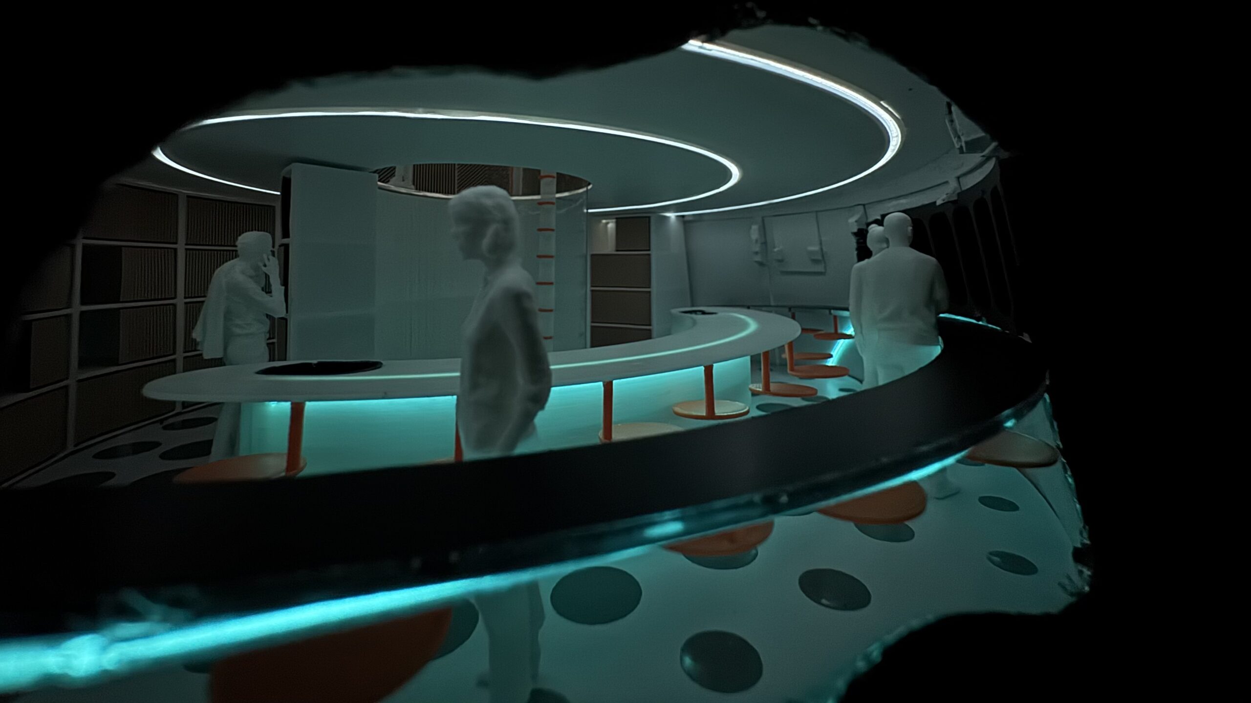
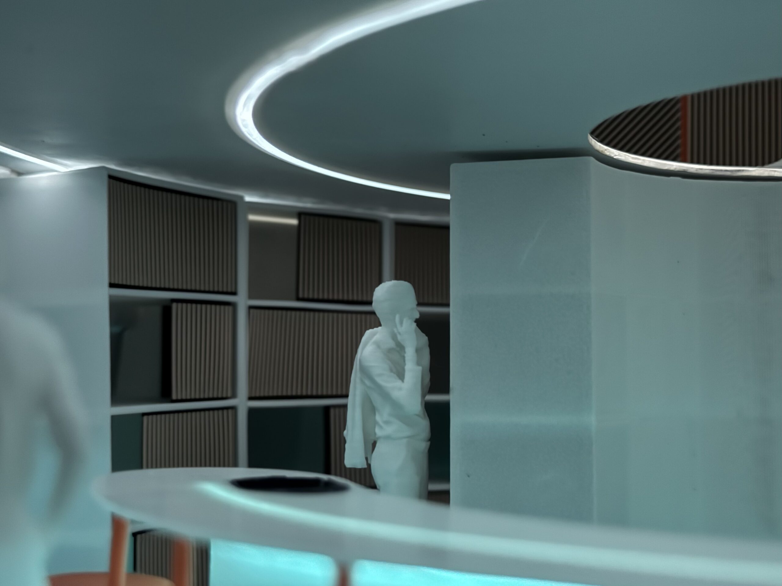
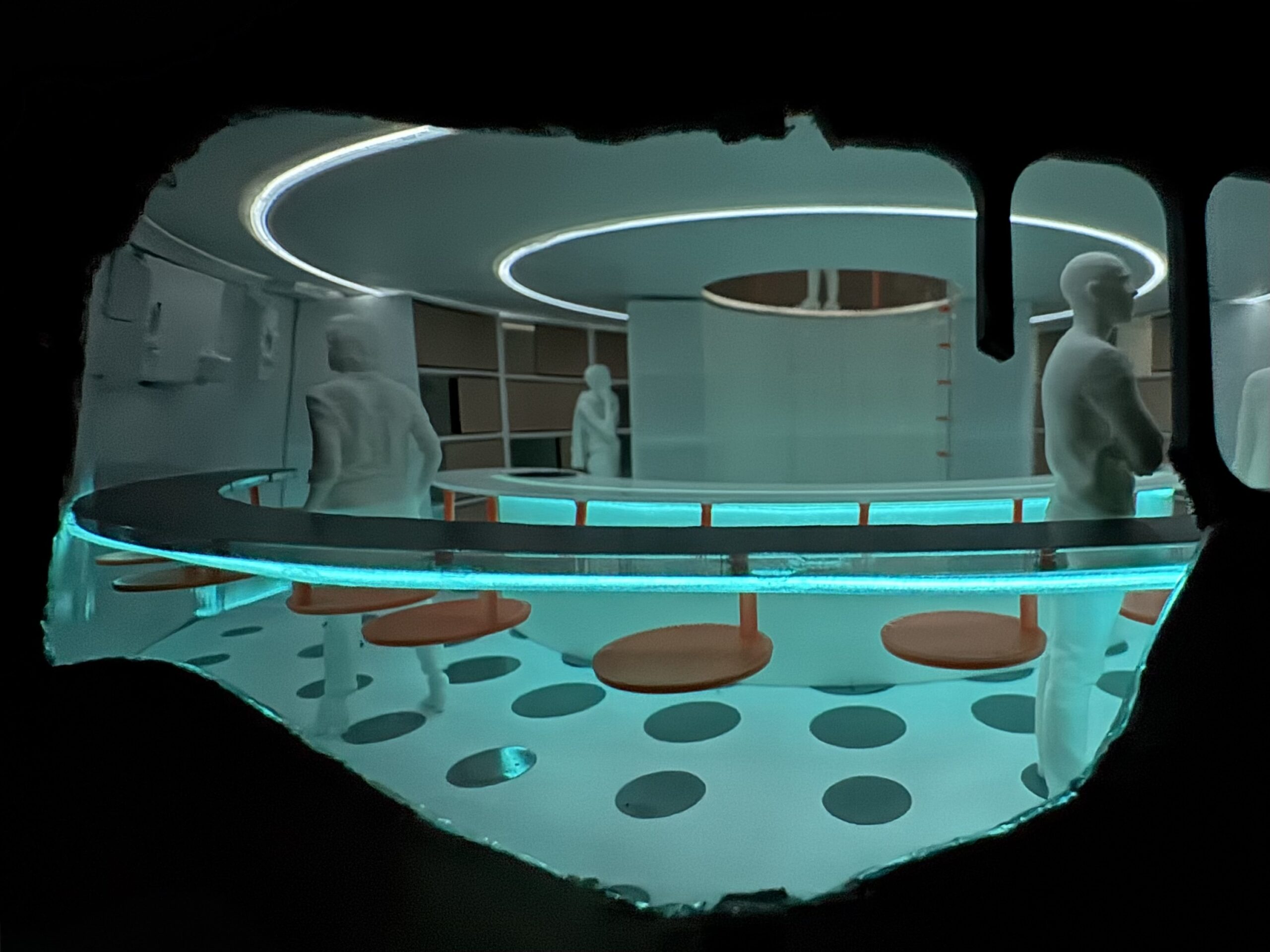
Bikes, treadmills, and digital resistance are here so bone and muscle survive the coast. Cardio is belt-loaded for micro-g. That hardware unfortunately is not in the render or the model.
Five full bathrooms, shower and toilet, share the deck. The count is for 100 people on shifts, and for a ship that may later run 1g. The stalls work as normal showers in gravity and as a wash volume in 0g.
Gym and wet rooms share the deck because the stack is tight, the deck is central, and you walk off a workout into a shower.
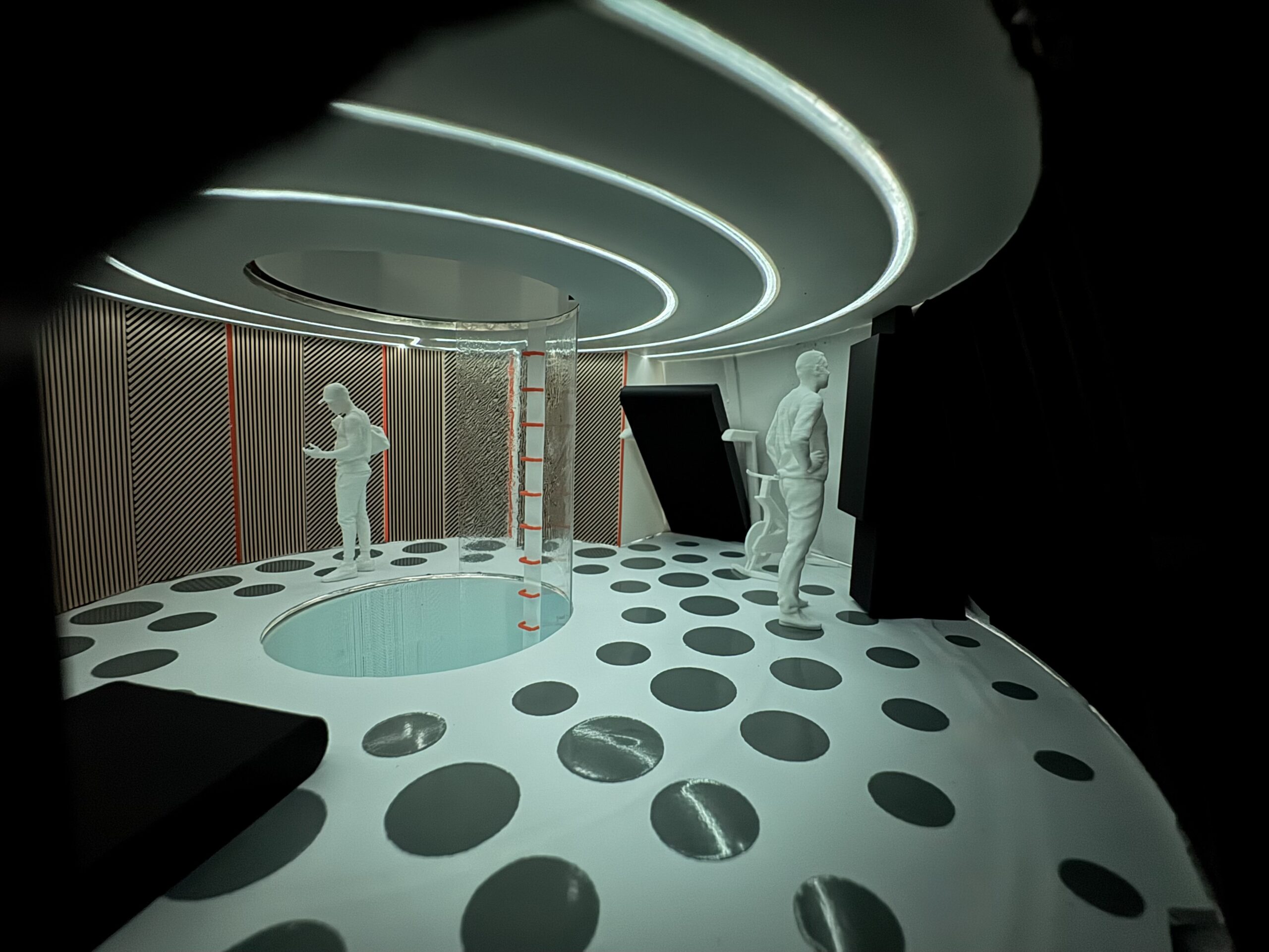
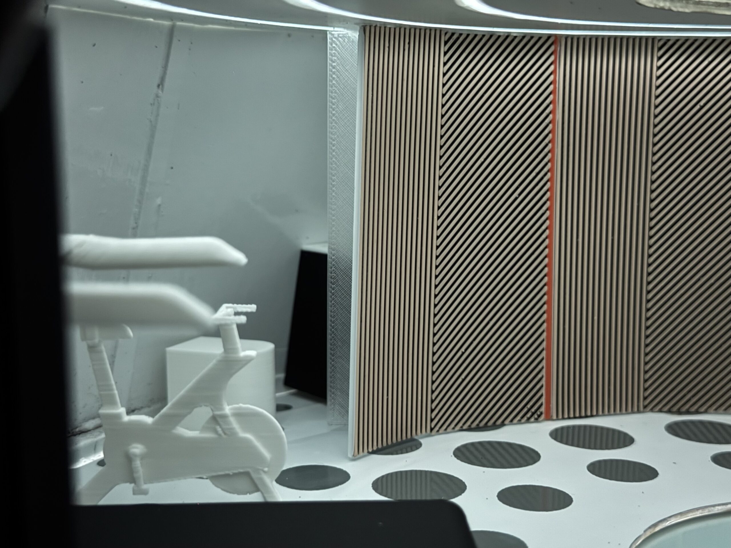
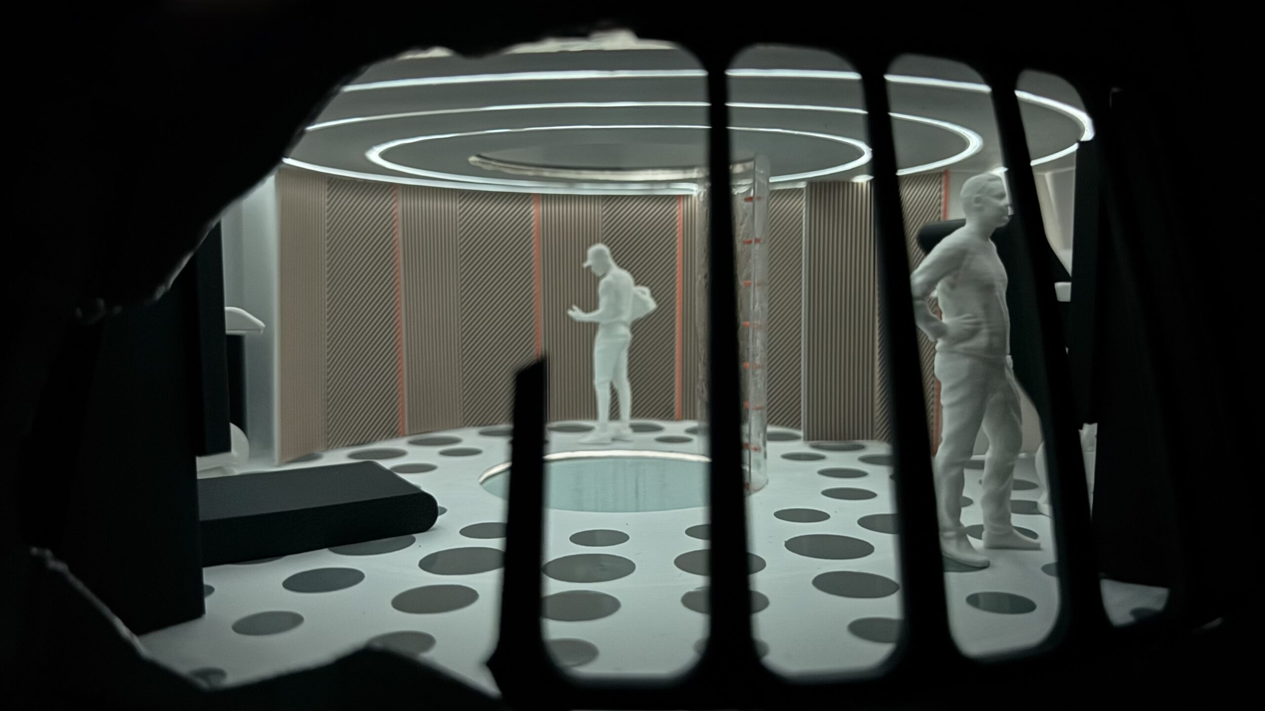
Work, recovery, and control share the diameter because the ship does not give you three extra decks.
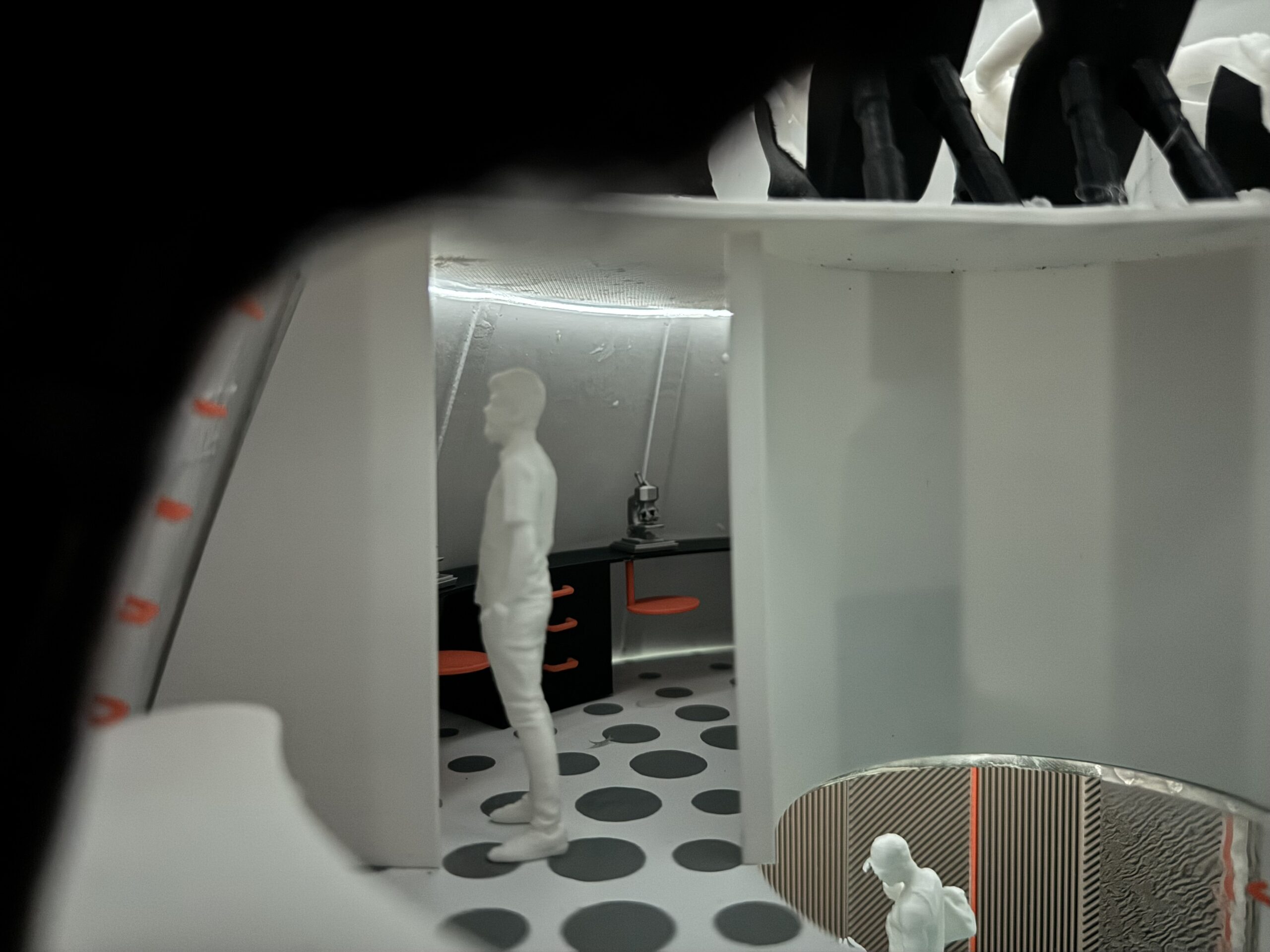
Command is a dedicated area to check systems through launch, cruise, landing. The lab has a subzero freezer, microscopes, and a sealed volume for opening or testing material that you do not want in the cabin air. Medbay is two hospital beds built for clinic or trauma, whichever shows up.
Five industry leading 3D-printers cover flight parts and crew projects. Bean bags strap down, and are there for 1g and for a break. The large window adds to the open plan and a place to look out.
Sep 3–5
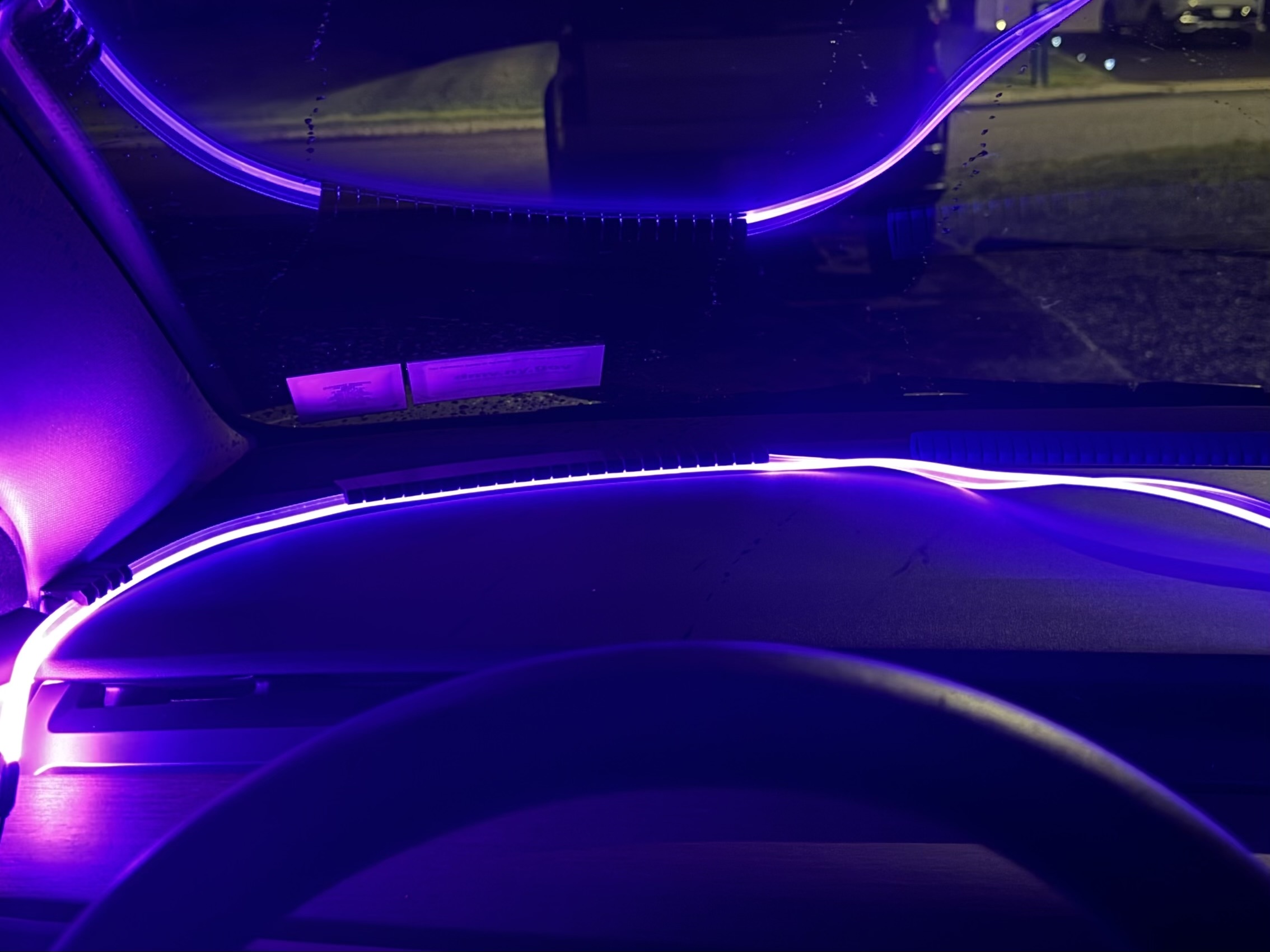
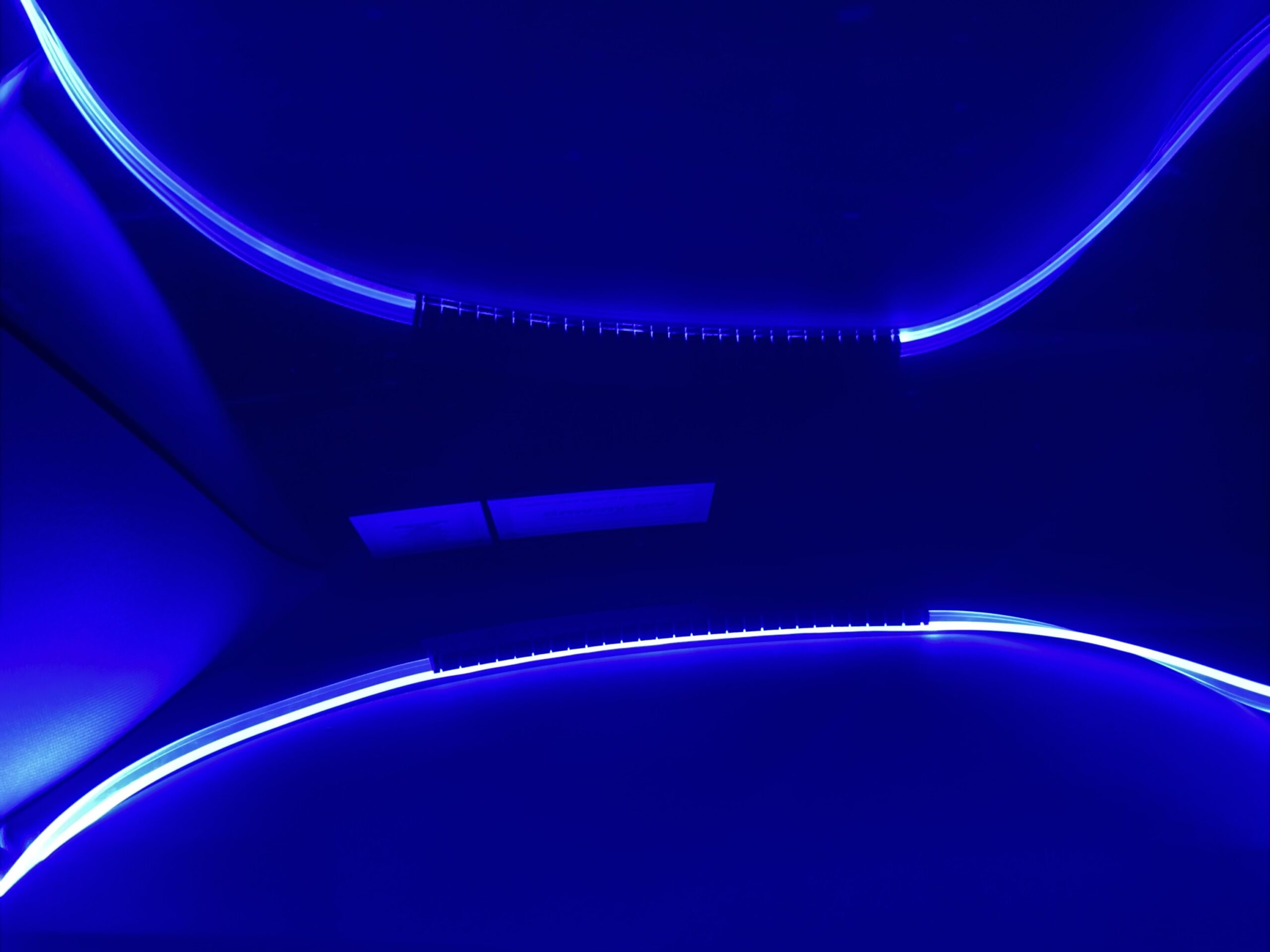
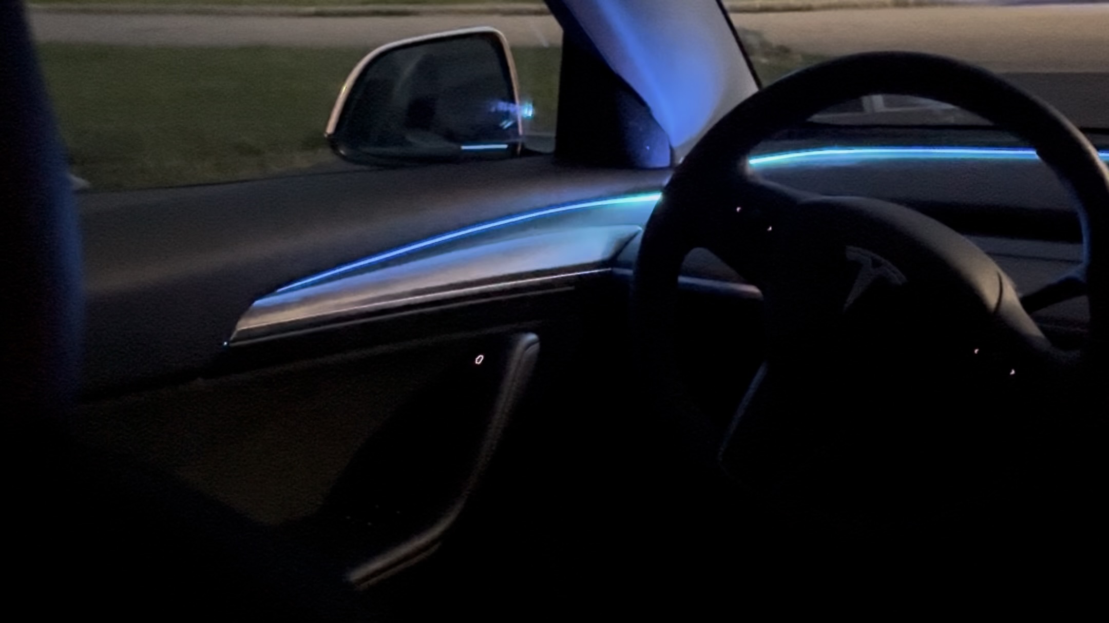
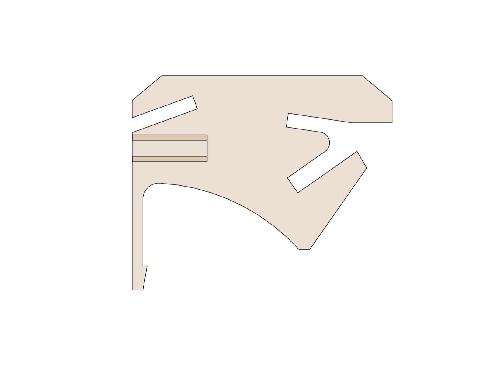
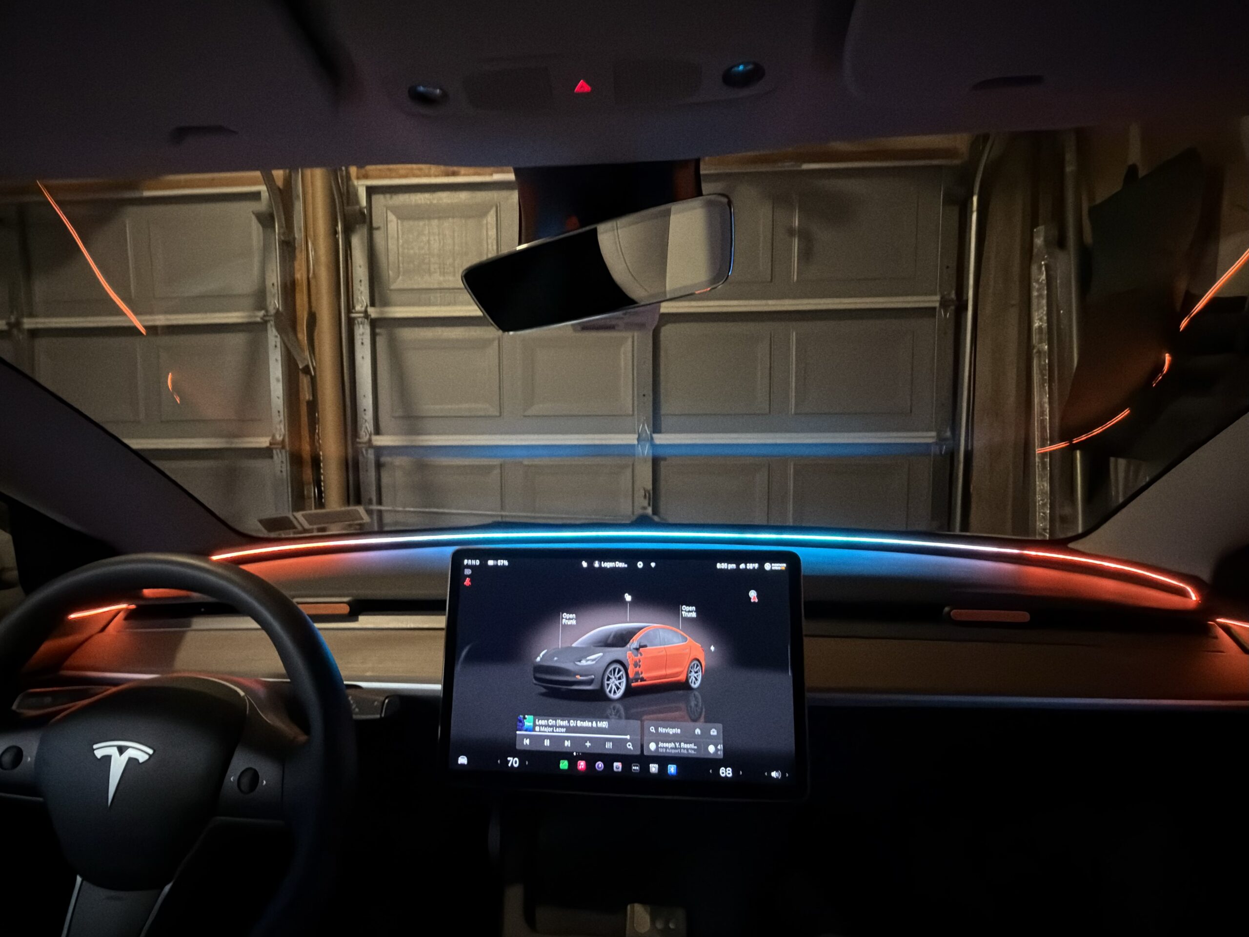
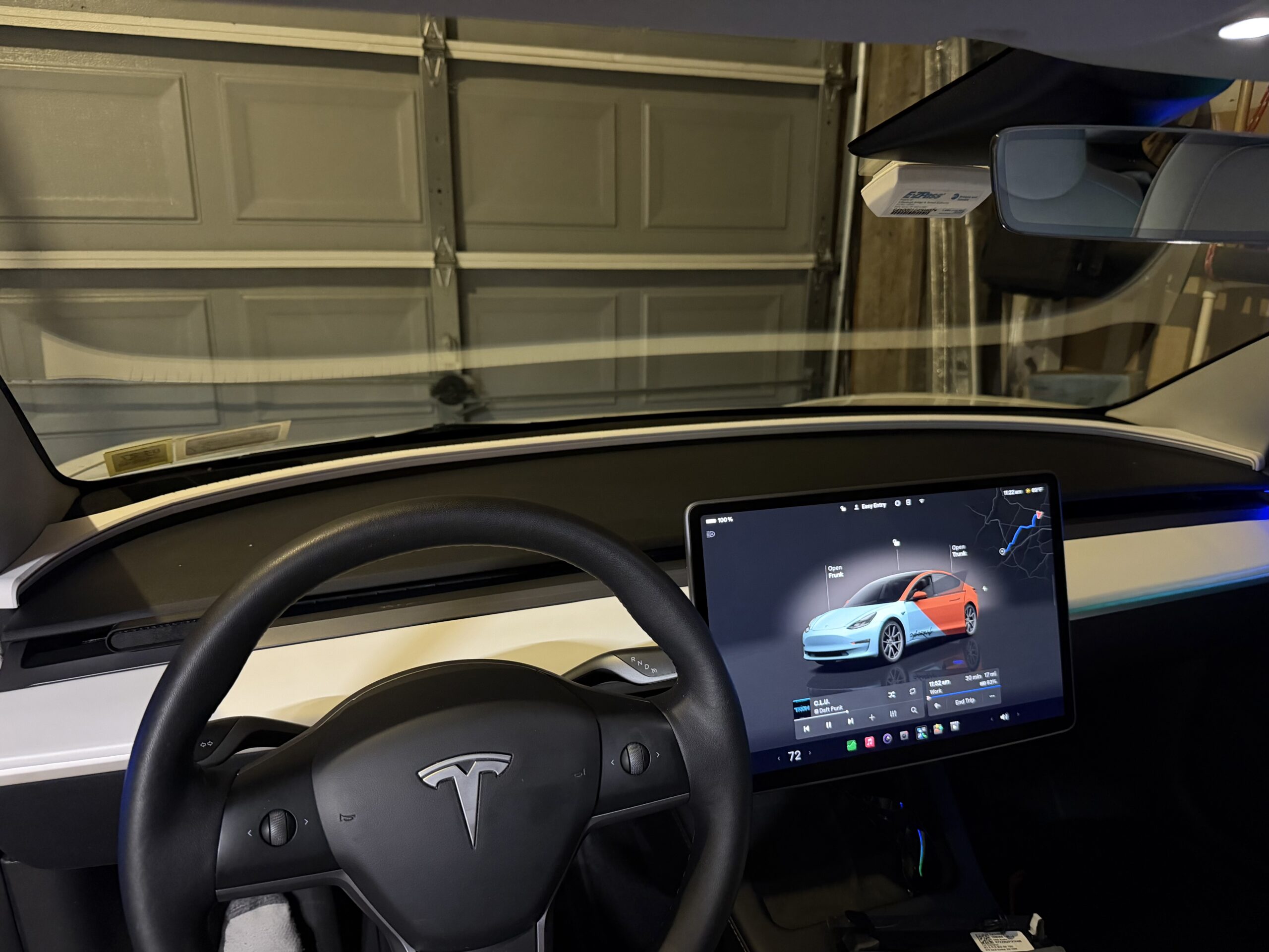
First complete build. Using a more cost effective option for lighting using optical LEDs, first full stack of printed parts, first leather wrap. This was the proof of concept, proving the shade could shade the light from the windshield, hold together in car heat, and provide ambient lighting. Everything after this is a revision of this object, not a new concept.
Sep 19–20
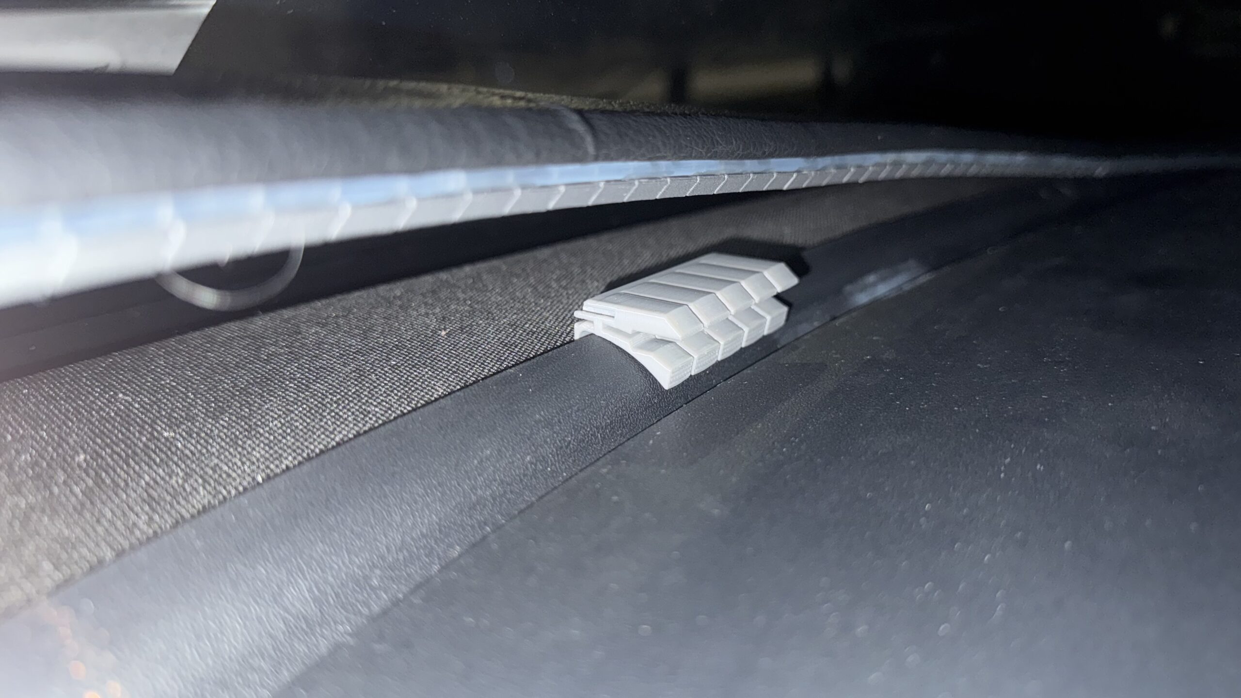
This iteration was a short loop, adding on a connector between parts instead of relying on only super glue and a second pass at the adhesive holding the leather. However issues with the connector and adhesive meant these changes didn’t stick as the long-term joint.
Jun 26–30
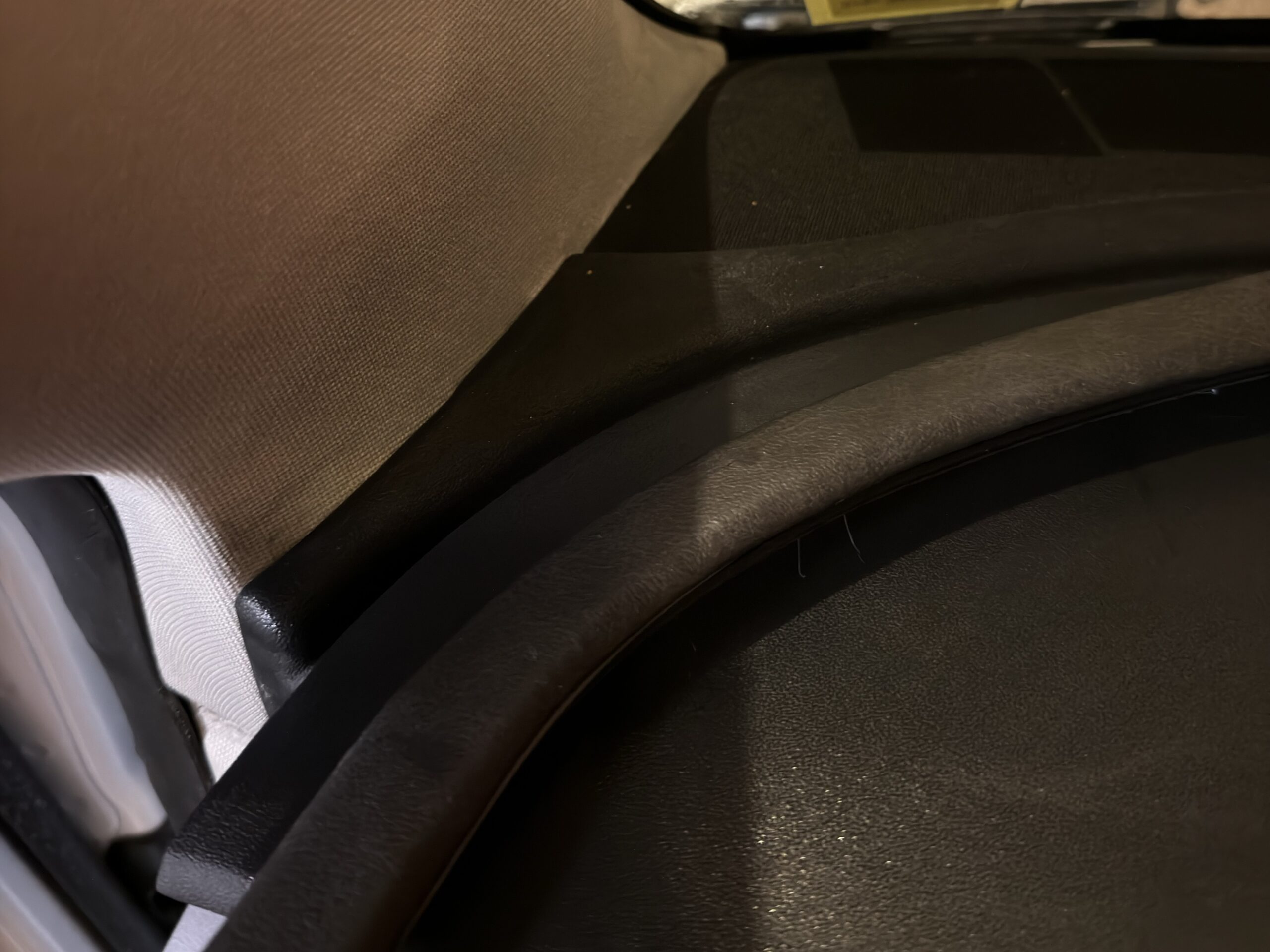
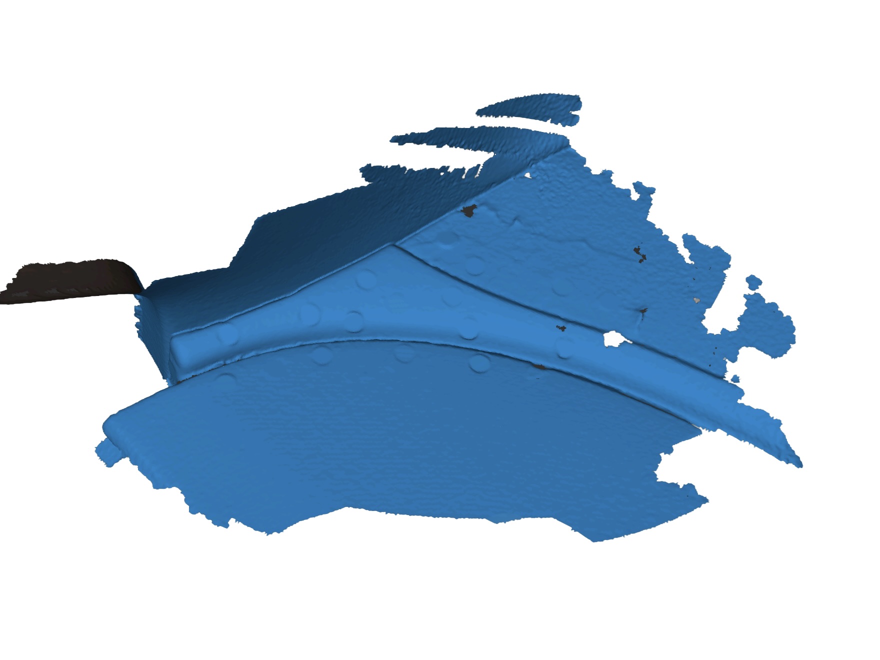
Having gained access to a 3D scanner, I was able to scan the corners and ends of the dash so the next parts matched the real object, instead of the parts weirdly bridging the corners. Jun 29–30: printed those pieces and added them to the October structure. No new light system, but a new wrap to fit the new parts. The main focus here was the fit, close the gaps the first geometry left at the edges, make it look more OEM.
Oct 7–17 · Jan 4
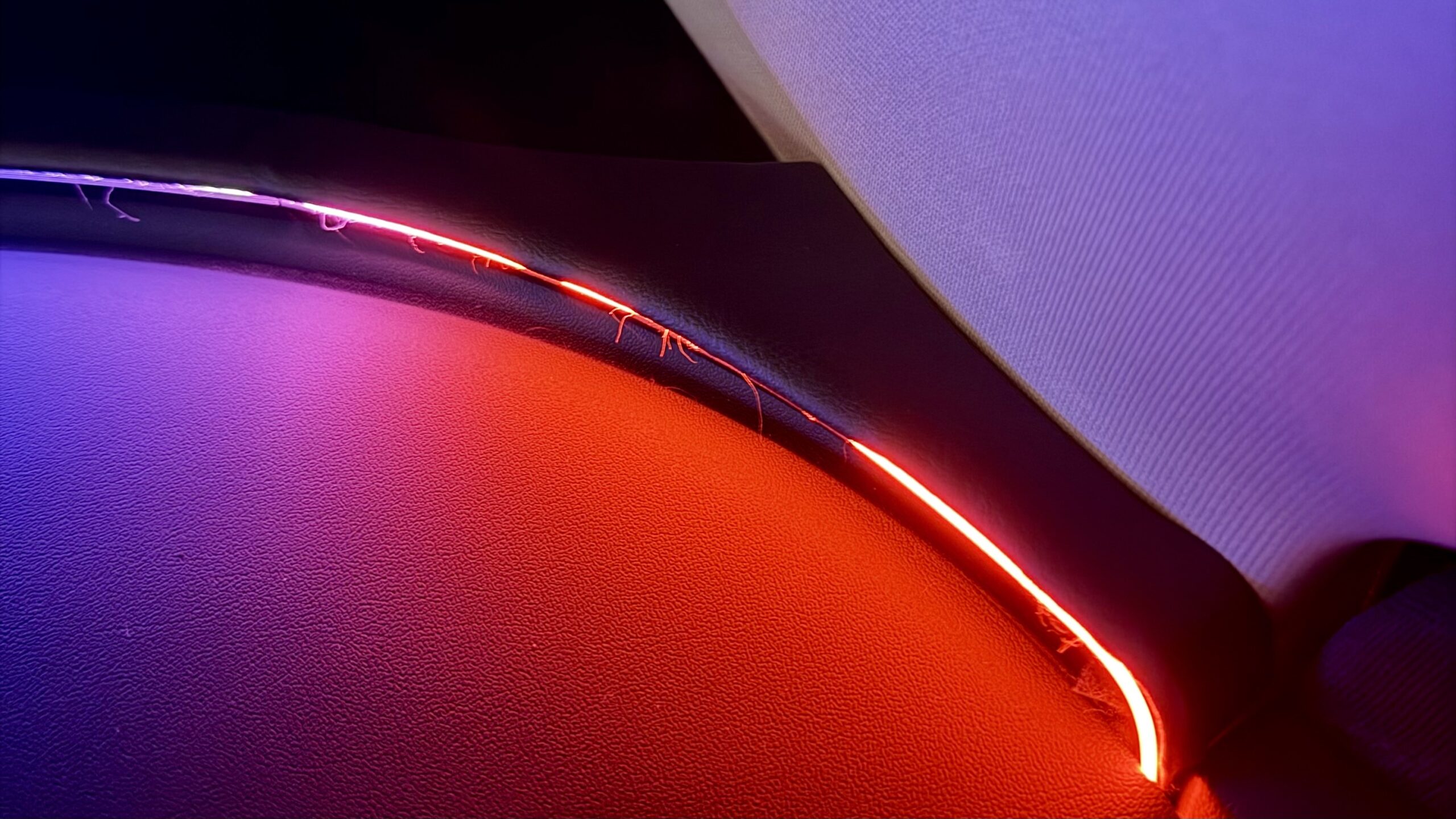
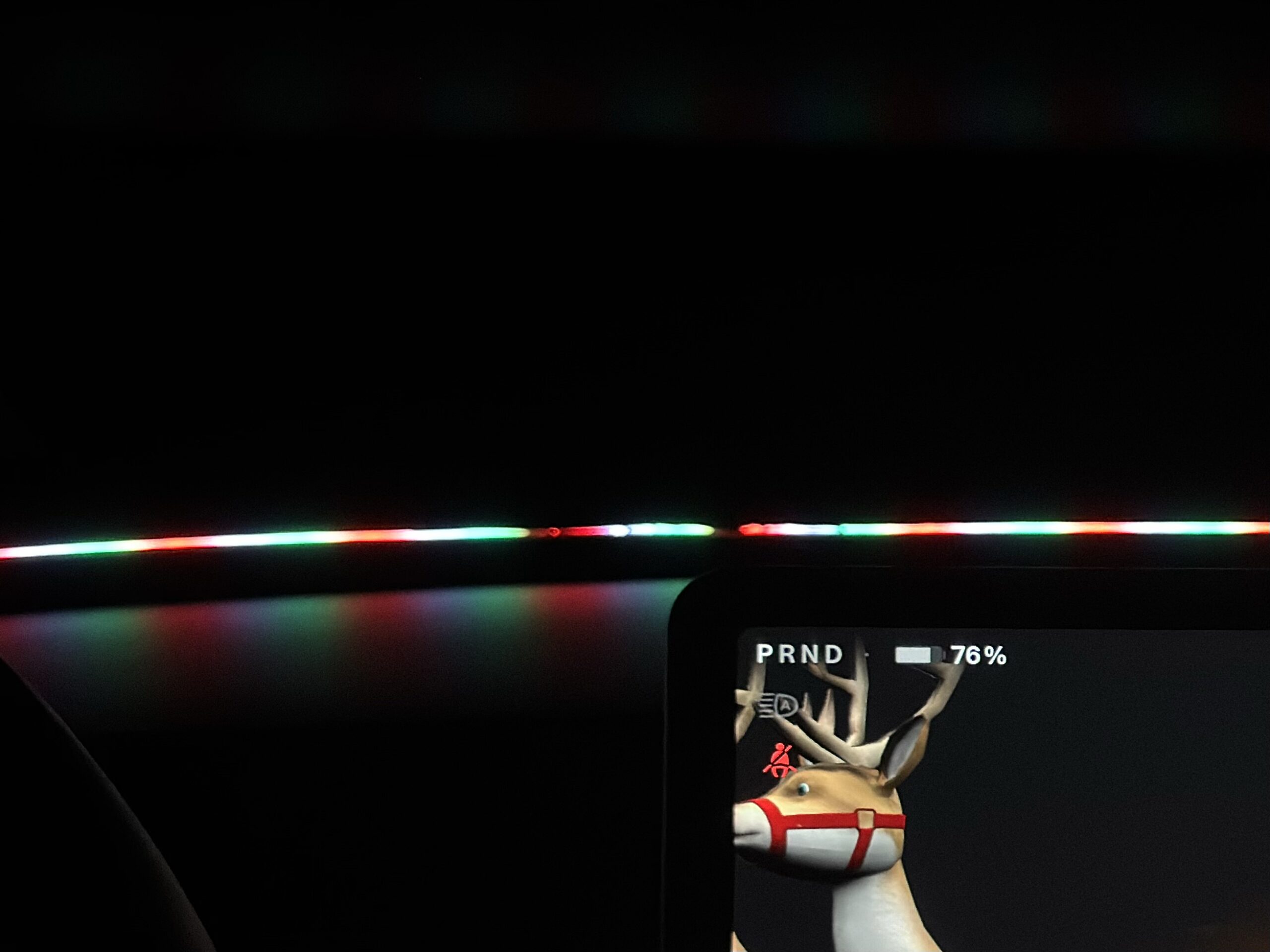
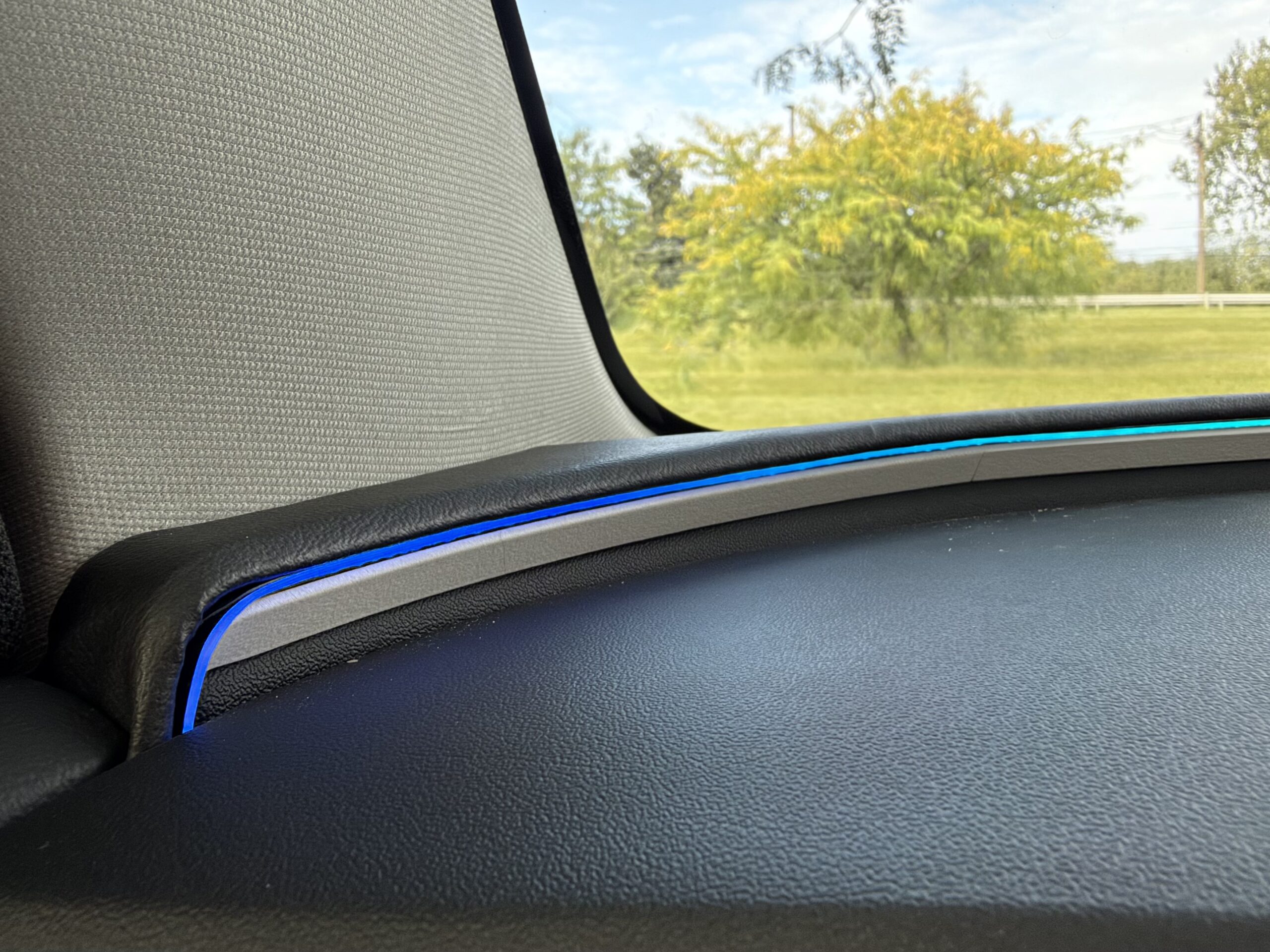
Oct 7–12, finished the 17th, was the real architecture change, swapping the optical LEDs out for micro LEDs, leather pinched between the LEDs and the rear of the shade, and a different connection between parts. These changes got rid of any reliance on any adhesives. This October stack is the structure later work sits on. Jan 4 was the same prints with new leather, no tears, cleaner LEDs, not a geometry change.

Sep 8–12
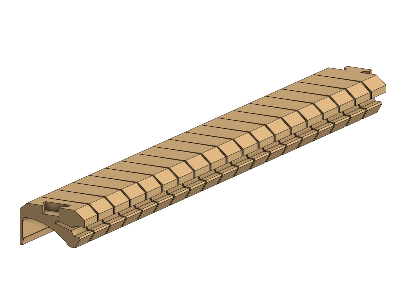
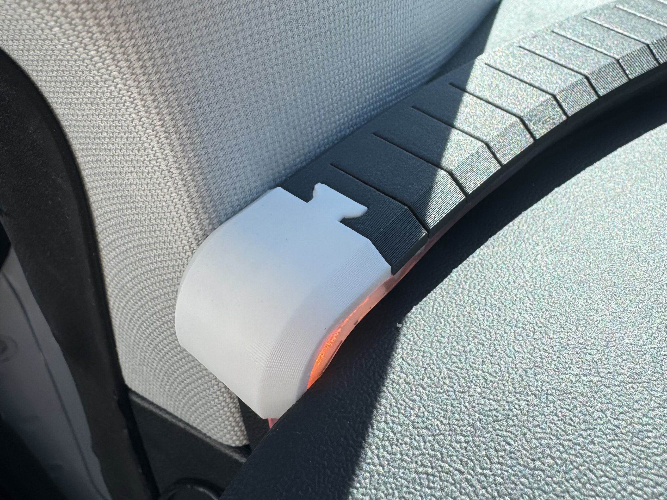
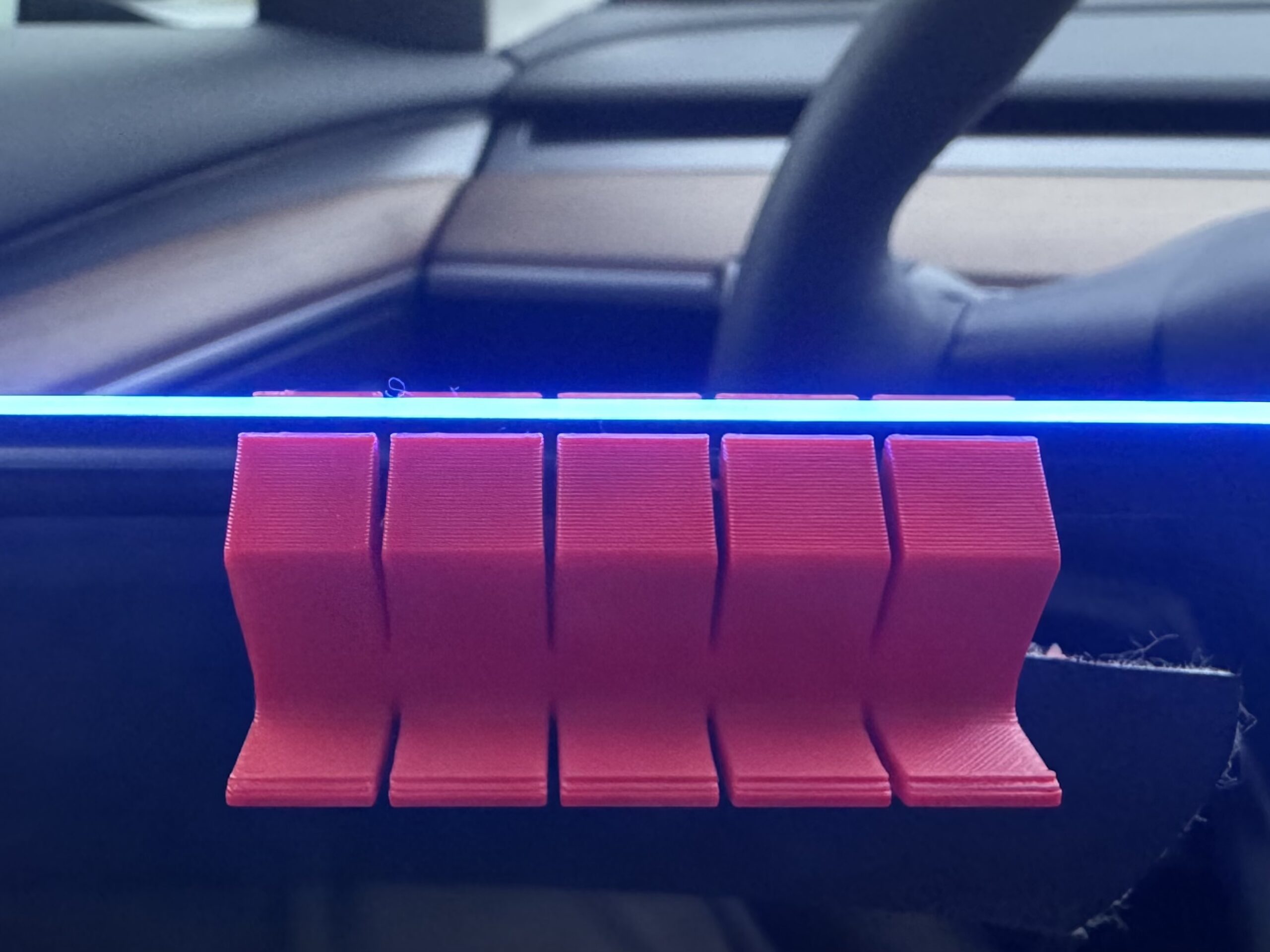
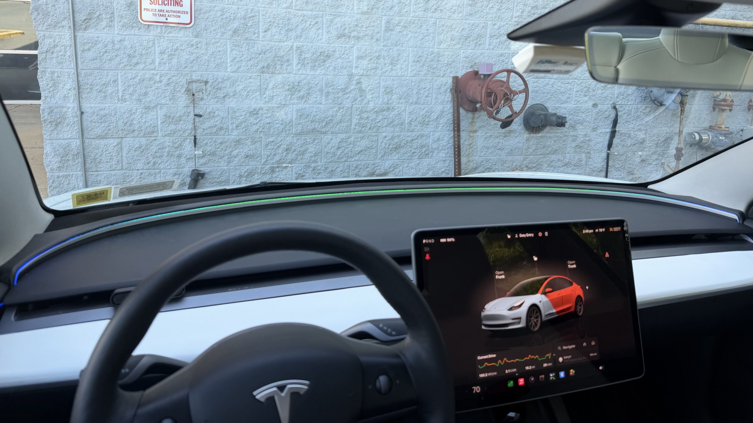
Cut the part count from 10+, depending on the iteration, down to 7. Pushed the relief cuts back so they are no longer visible from the front. Reprinted the full stack in white PETG-GF and tried to reuse the existing leather. Too many holes from pulling it on and off, making the LEDs appear messy, a new wrap on the 12th made this the finished unit.
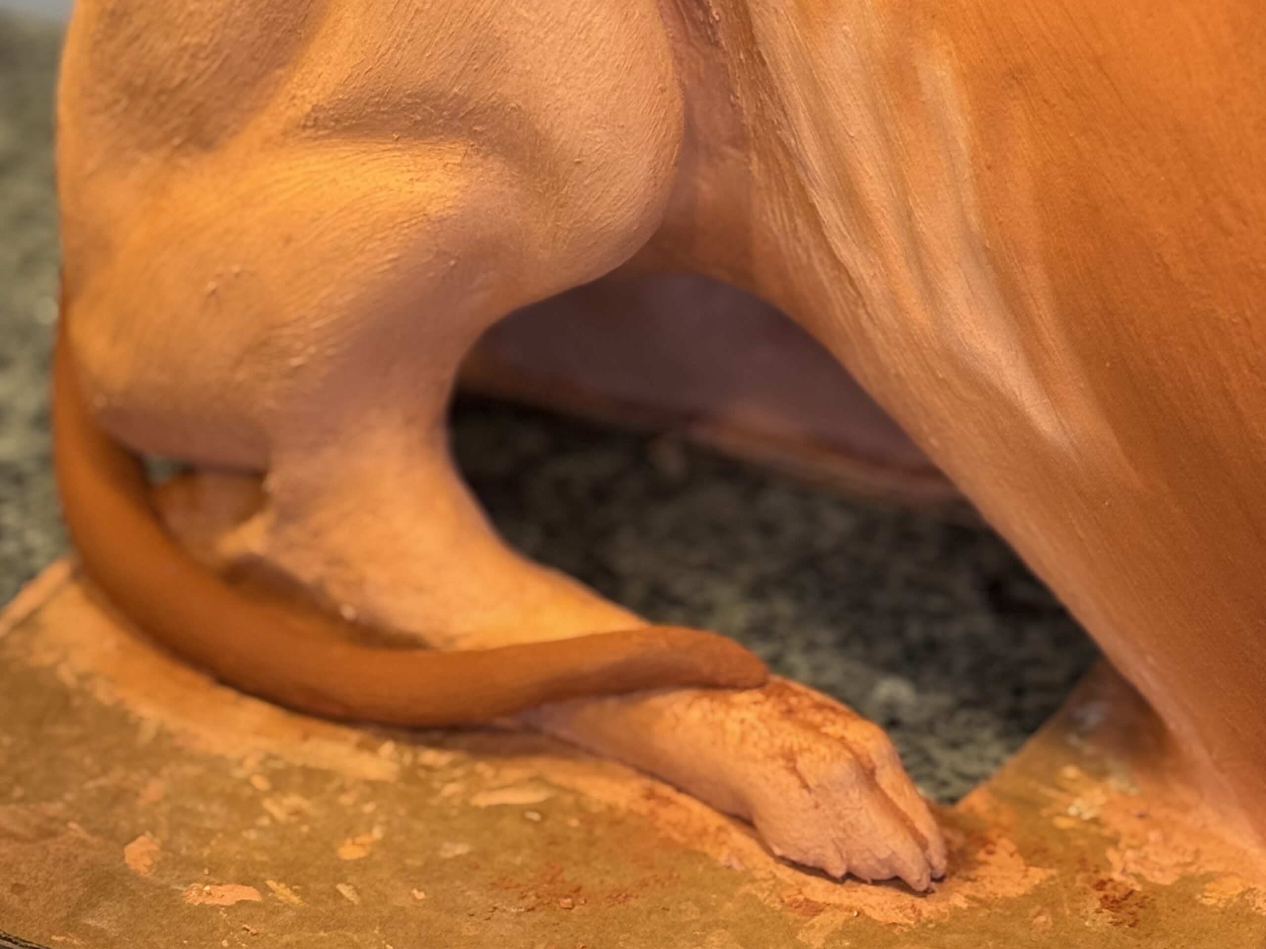
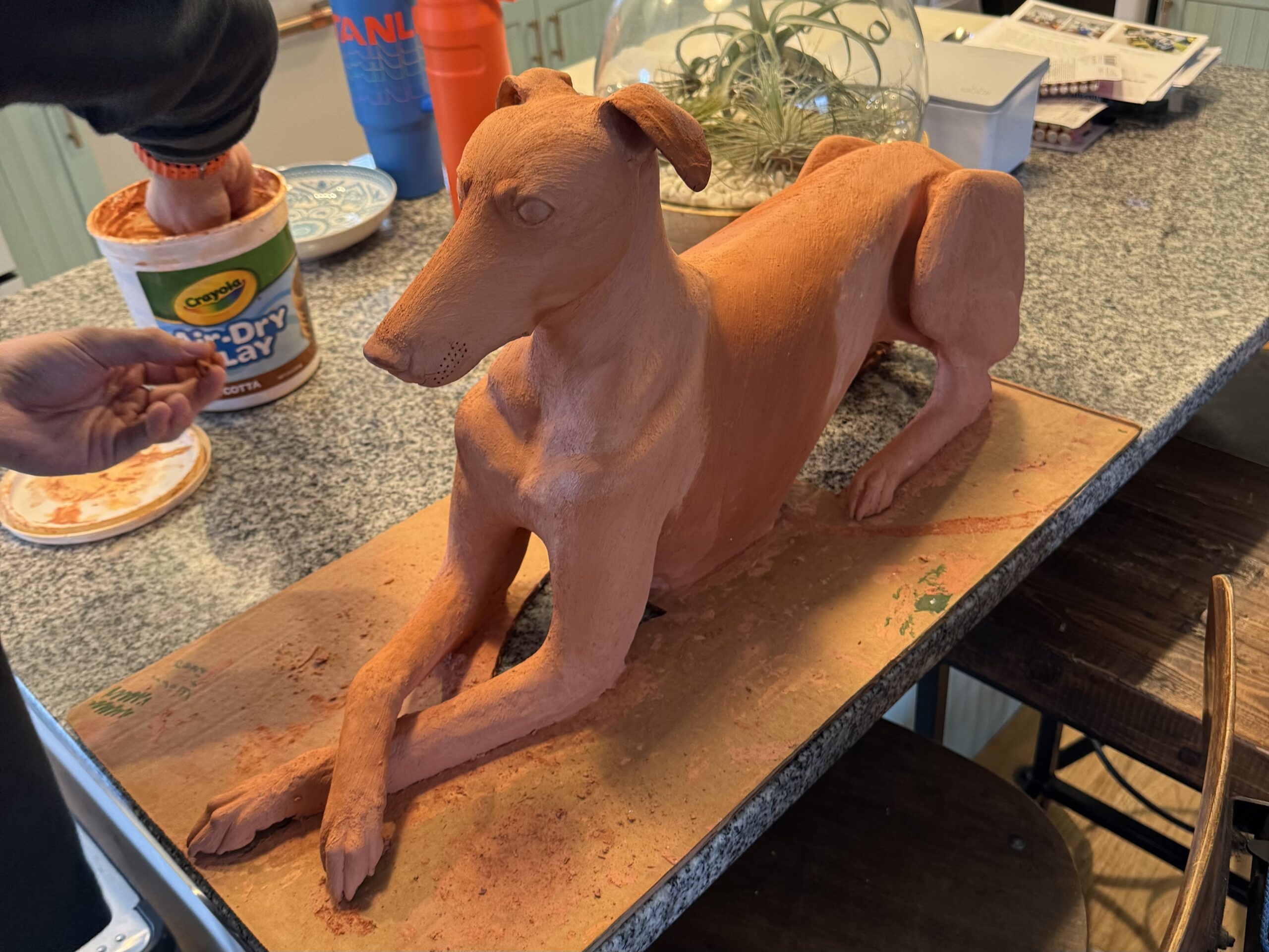
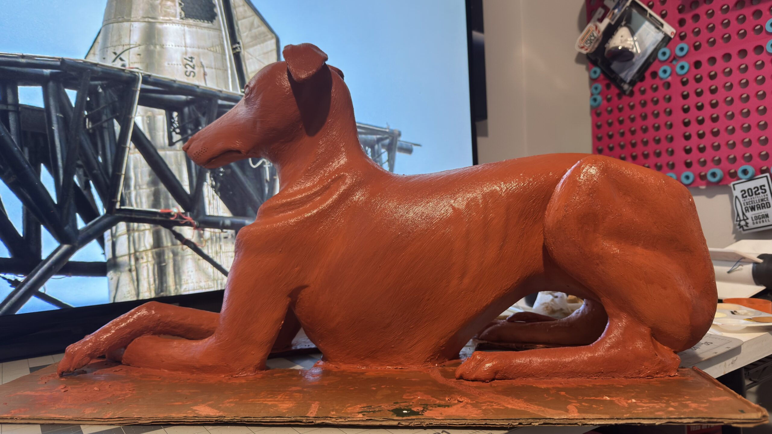
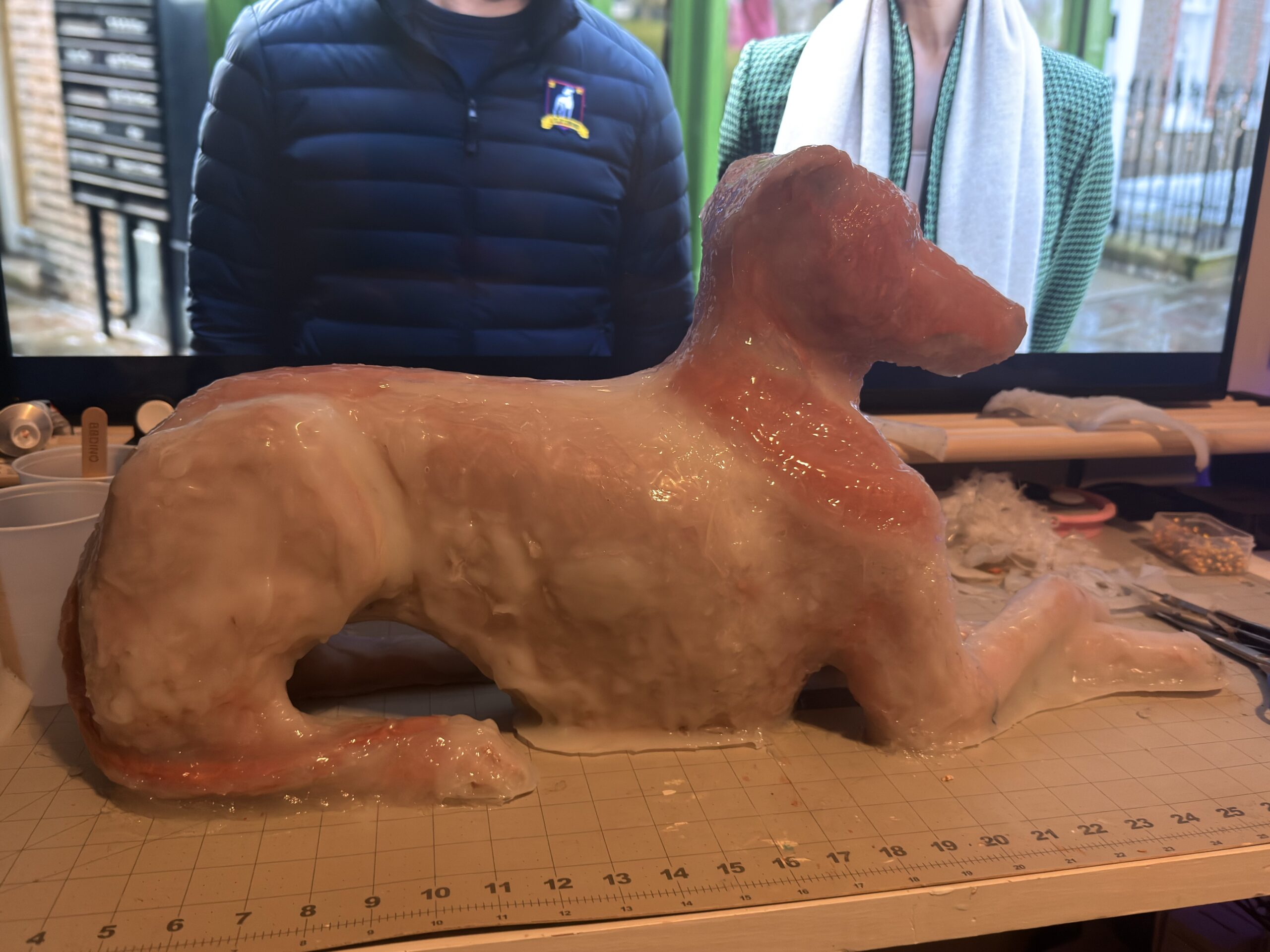
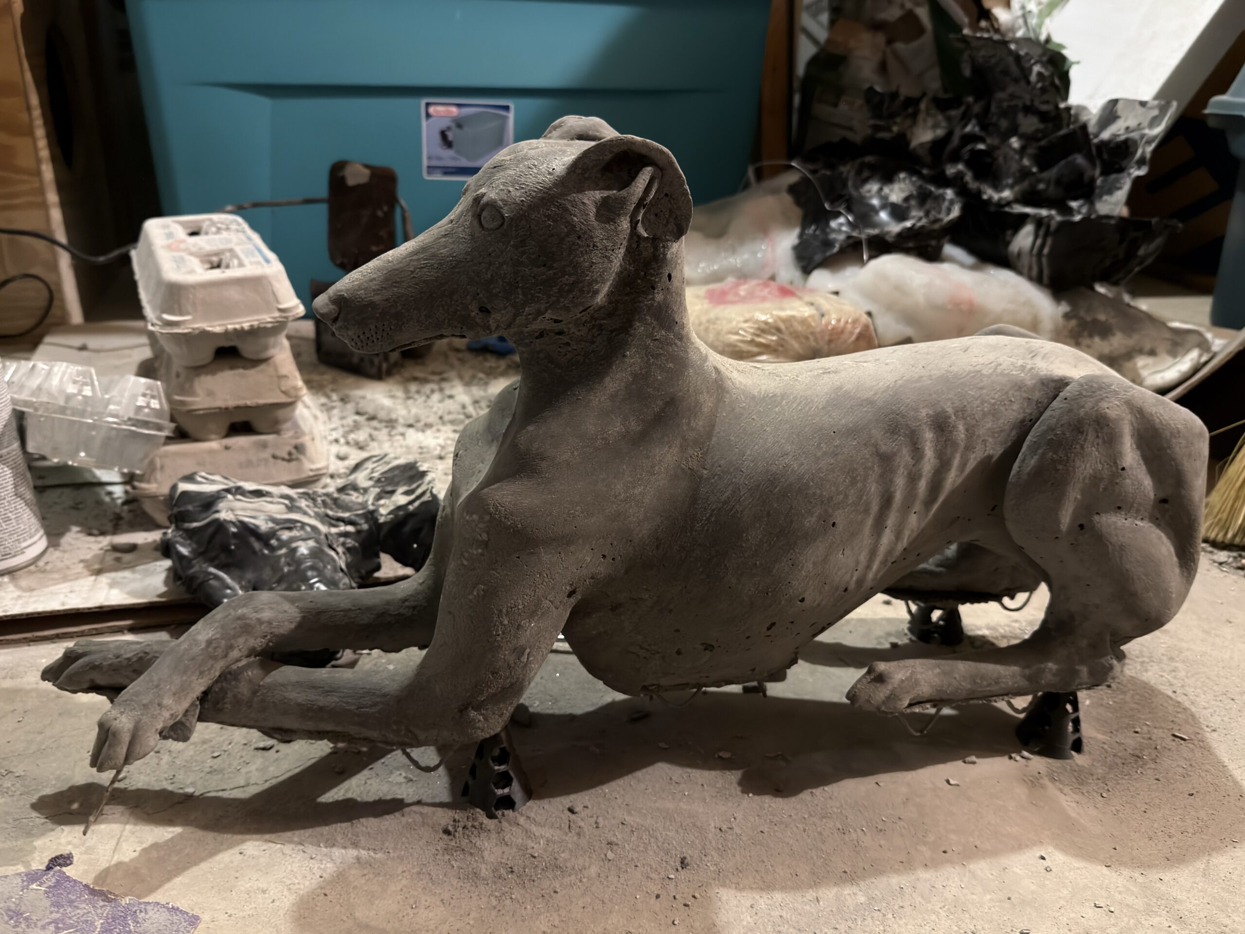
The first sculpt is the one she approved fully, with ears out, legs free, pose held by the cardboard and papier-mâché underneath. Clay went on in passes over a few months, checking with her so the sculpt stayed true to what she wanted but couldn’t find. That sculpt was the master for the first mold. It did have a couple flaws in areas where the sculpt was thin like the ears and legs, where prone to breaking.
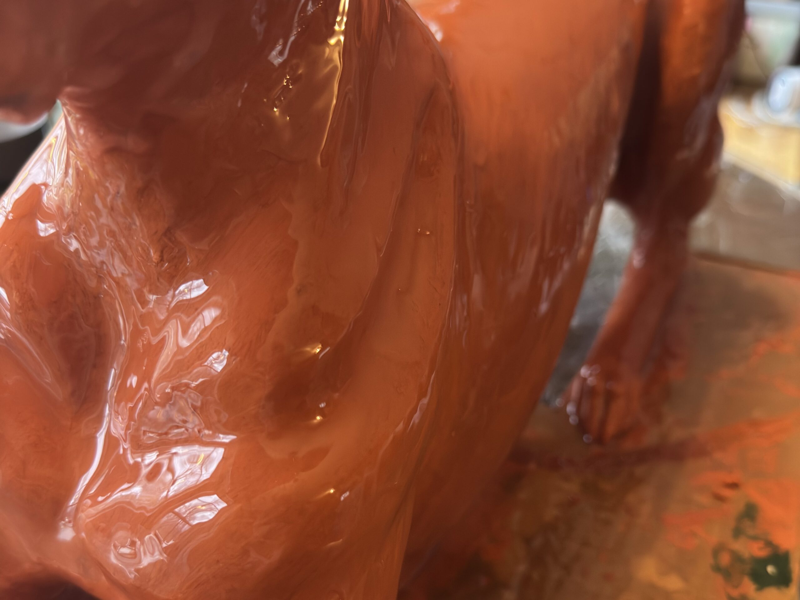
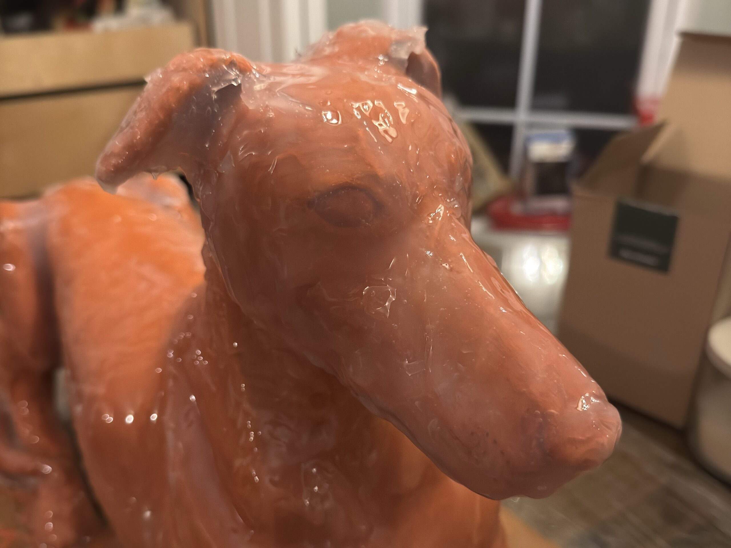
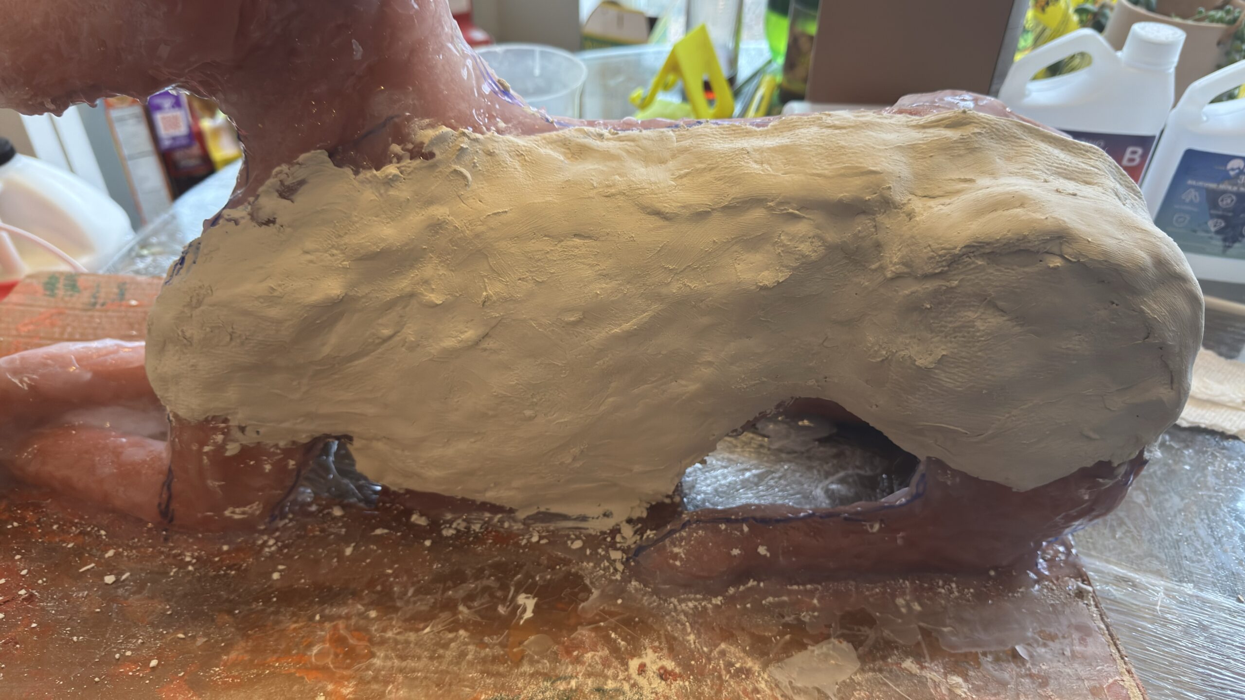
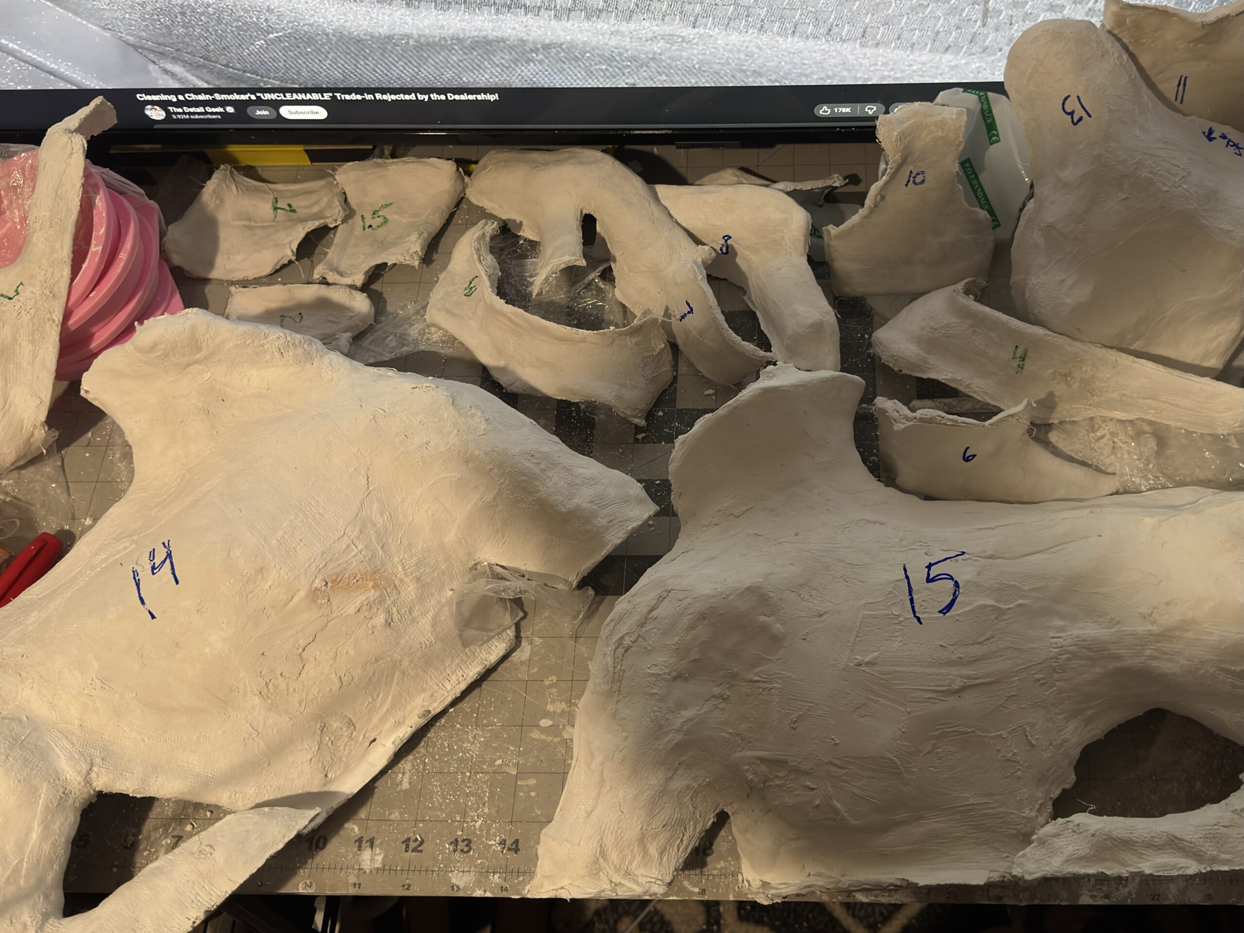
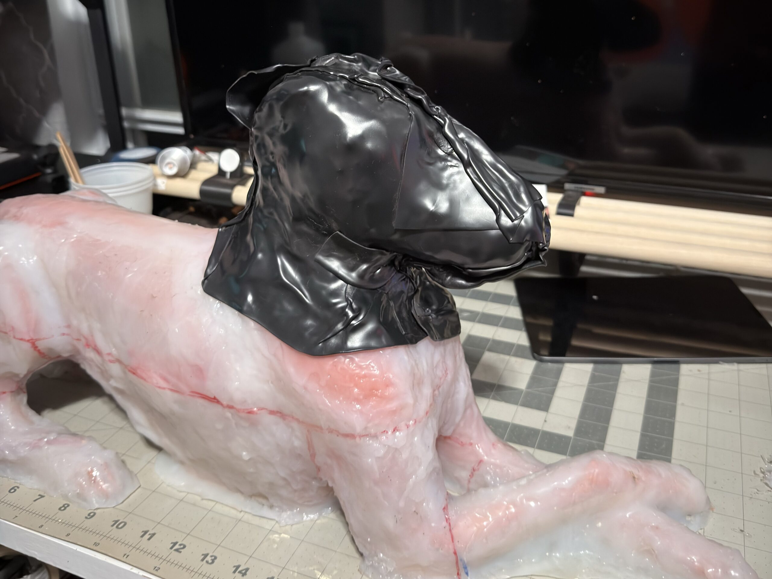
The silicone went on only thick enough to capture the detail in the sculpt and to not tear. A multi-part plaster jacket went over it so that thin skin had rigidity without becoming a solid block of silicone. The split let me get the dog out and still keep the surface. Plaster was the cheap rigid shell. It worked for a first mold but needed extensive repairs after each pour. That made plaster not a viable solution for long-term use.
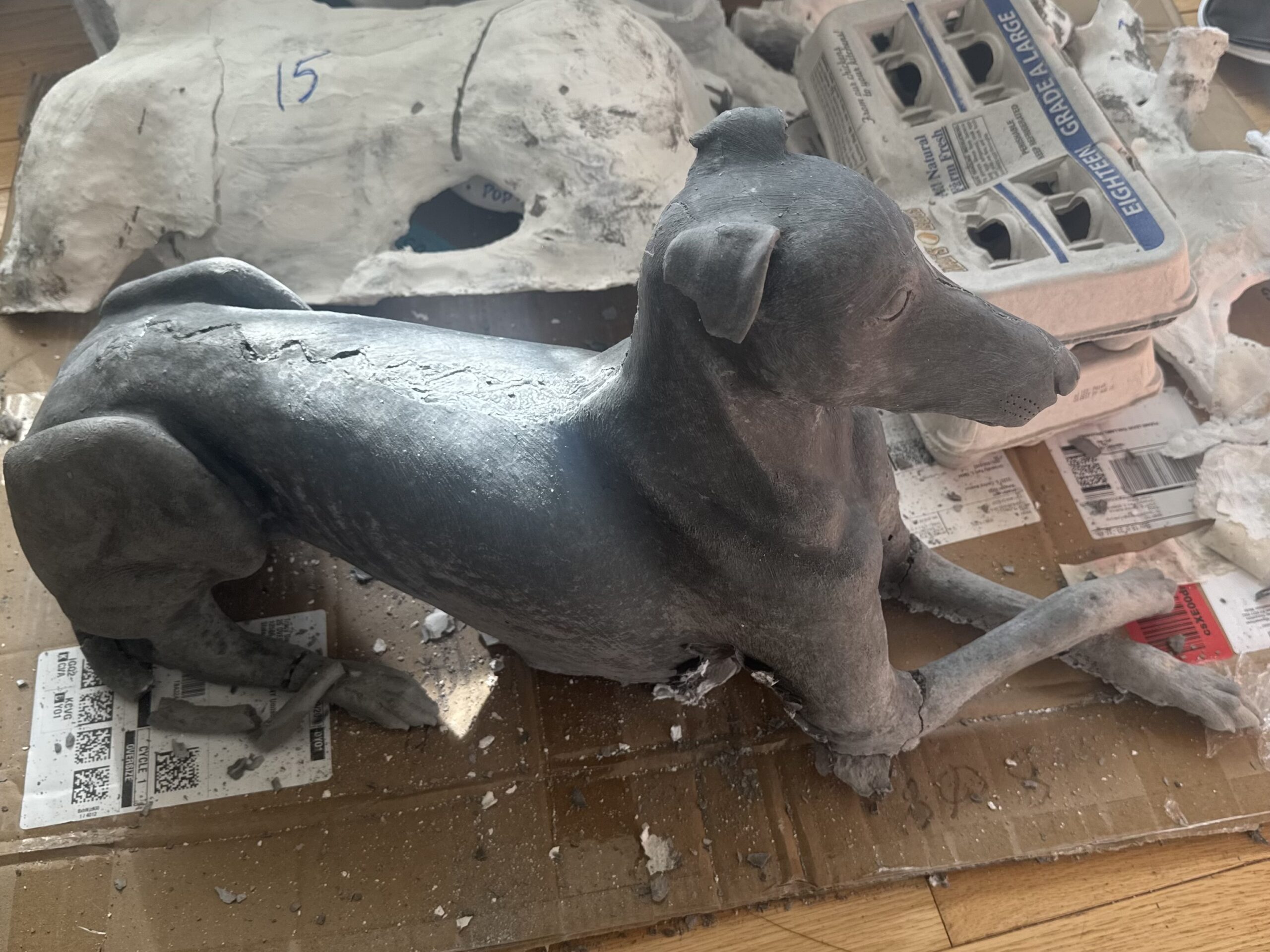
The first casts were my first time working with concrete. They came out both rougher and better than I expected, with broken legs, ears, and voids, but the detail captured in the mold was impressive. By the fourth pour the molding and demolding process made sense. The ears and tail were already the problem. They were thin on the original, and even with wire and rebar they broke on every demold. The third and fourth casts were the ones I could repair enough to finish.
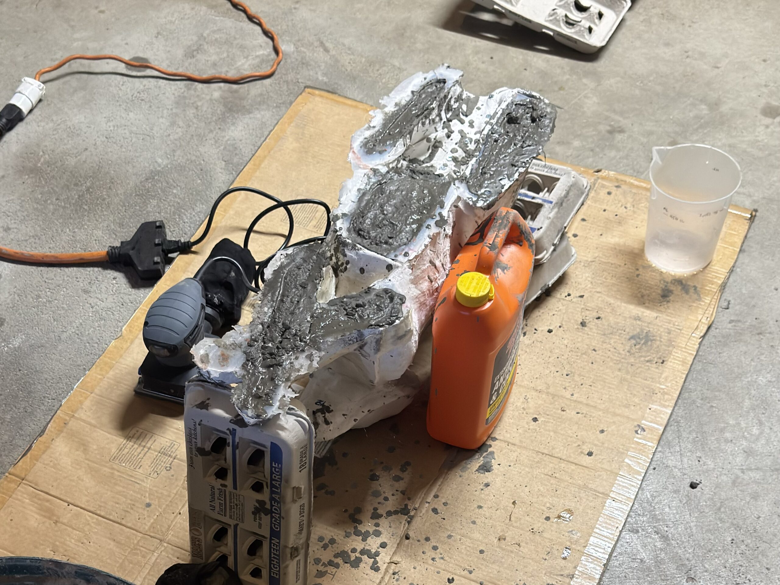
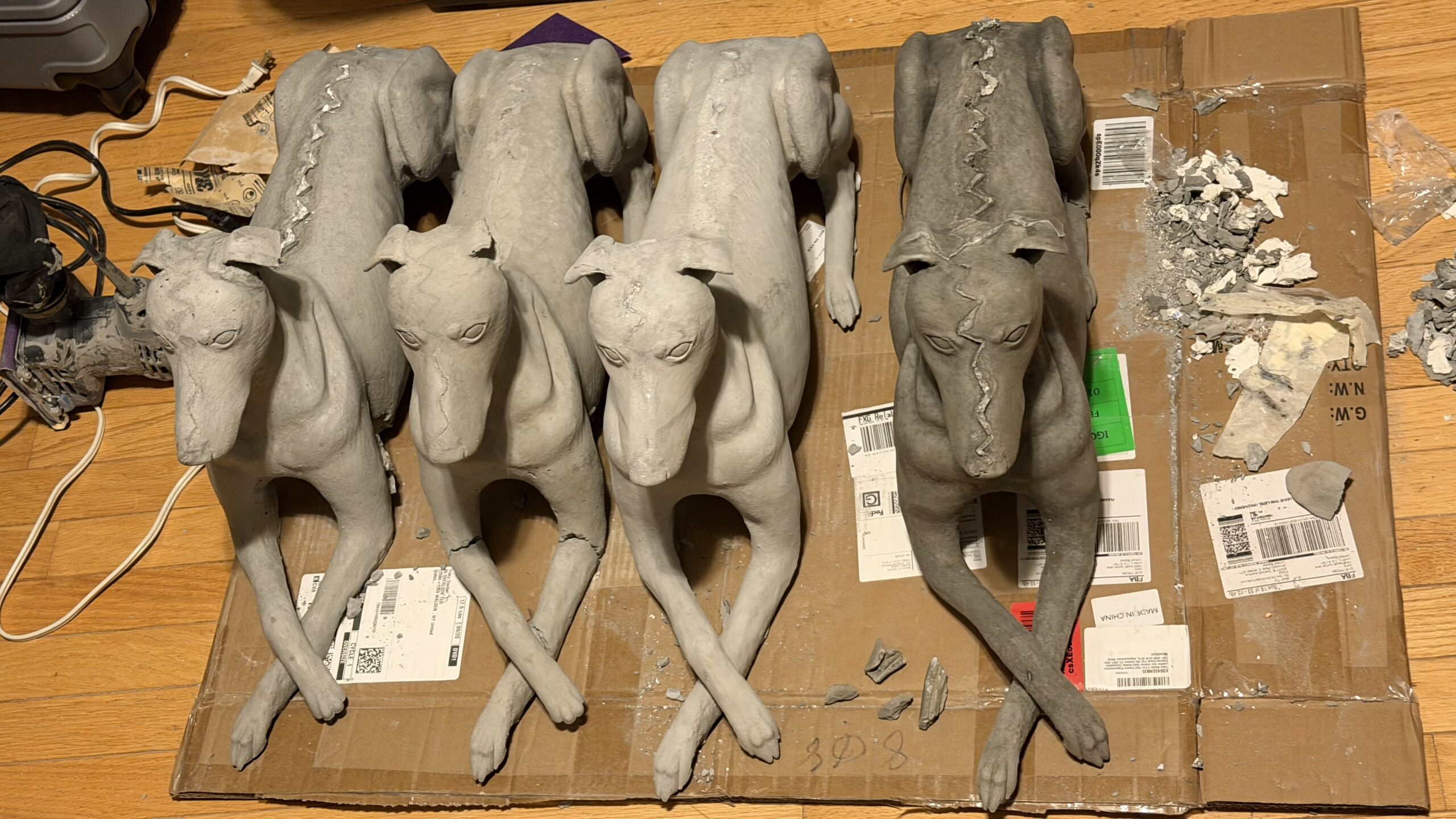
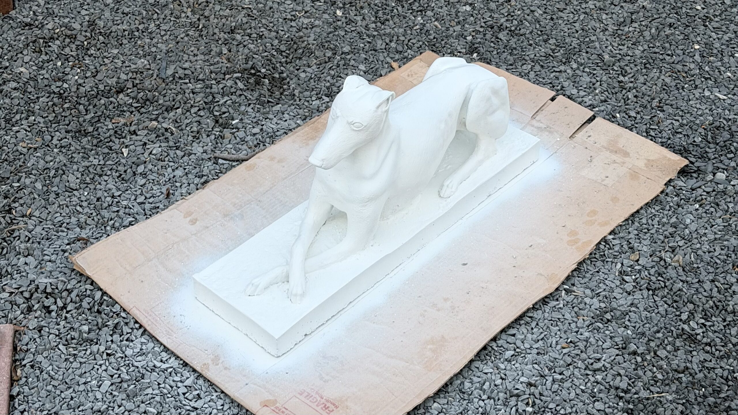
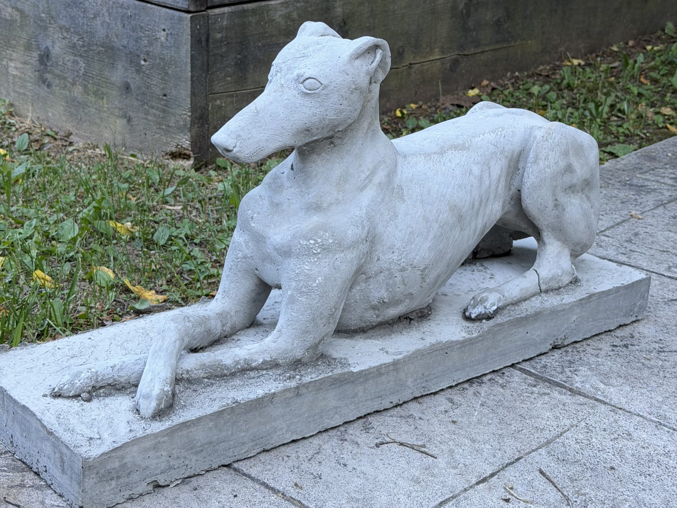
Those two had any air bubbles filled, surfaces sealed, sprayed with a concrete texture, and handed over on 12.28.25. They held for a while in the house. Then the parts I had been repairing started to break again, from balls tossed around the house to the rear leg with the tail randomly crumbling. The gift worked. The structure did not.
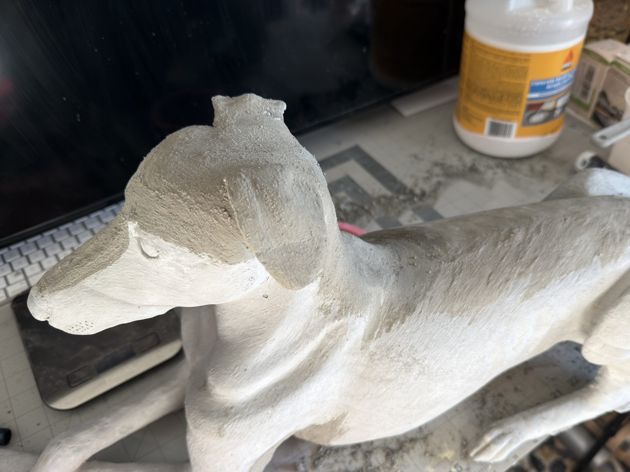
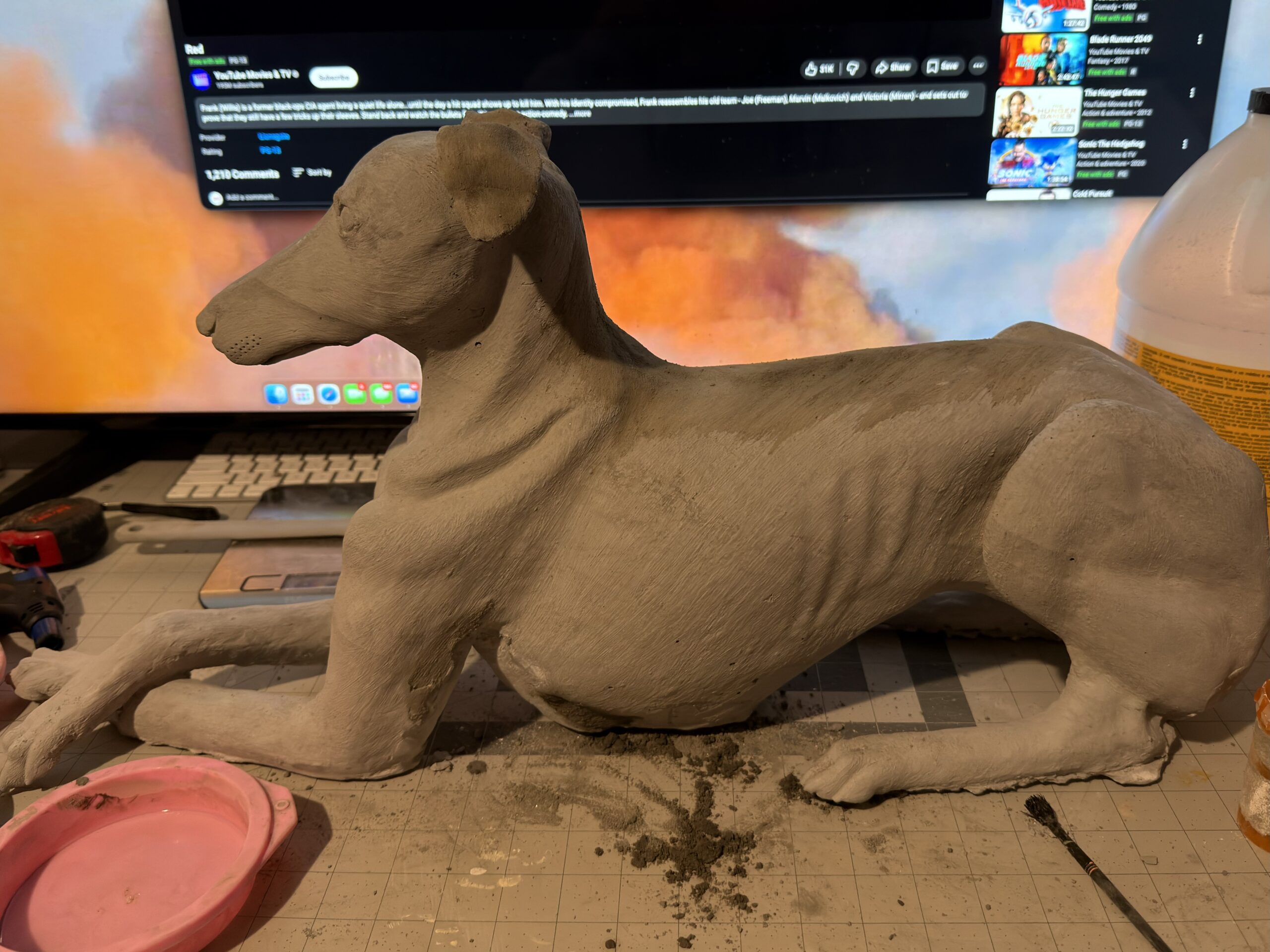
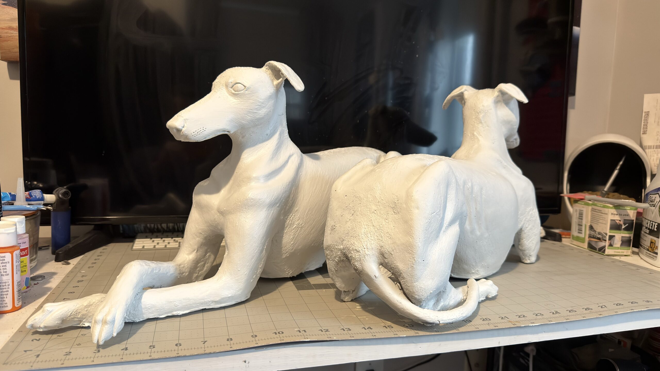
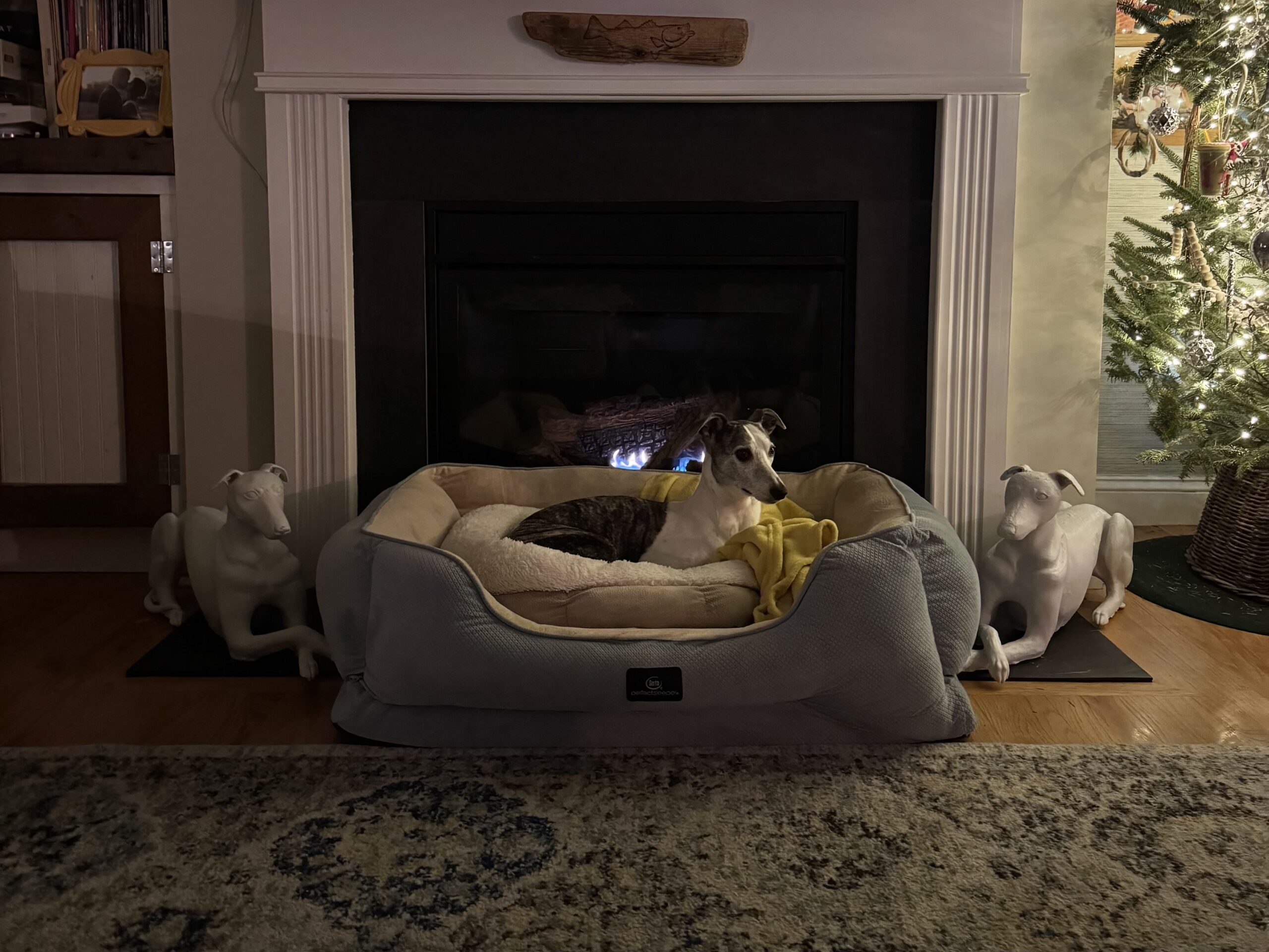
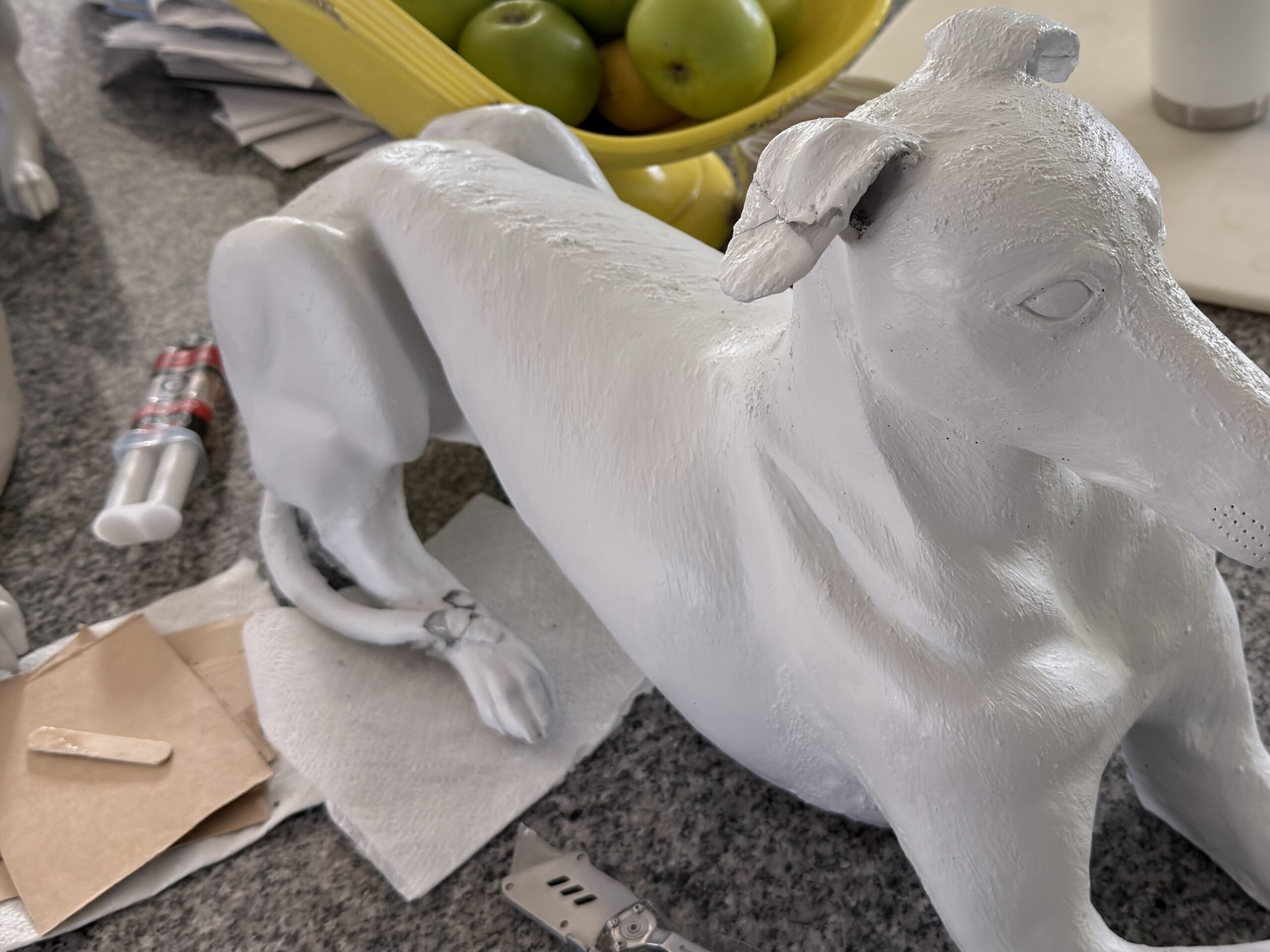
The second body started after she had lived with the first pair and could point at what was missing and the weak points. The ears came off and were remolded to tuck back. That was not her first choice, which is why version one had them out, but it was the compromise that would survive. The tail got a hidden added structure tying to the rear leg so the joint was strong without reading as a brace. A few small surface changes from those daily notes were made as well.
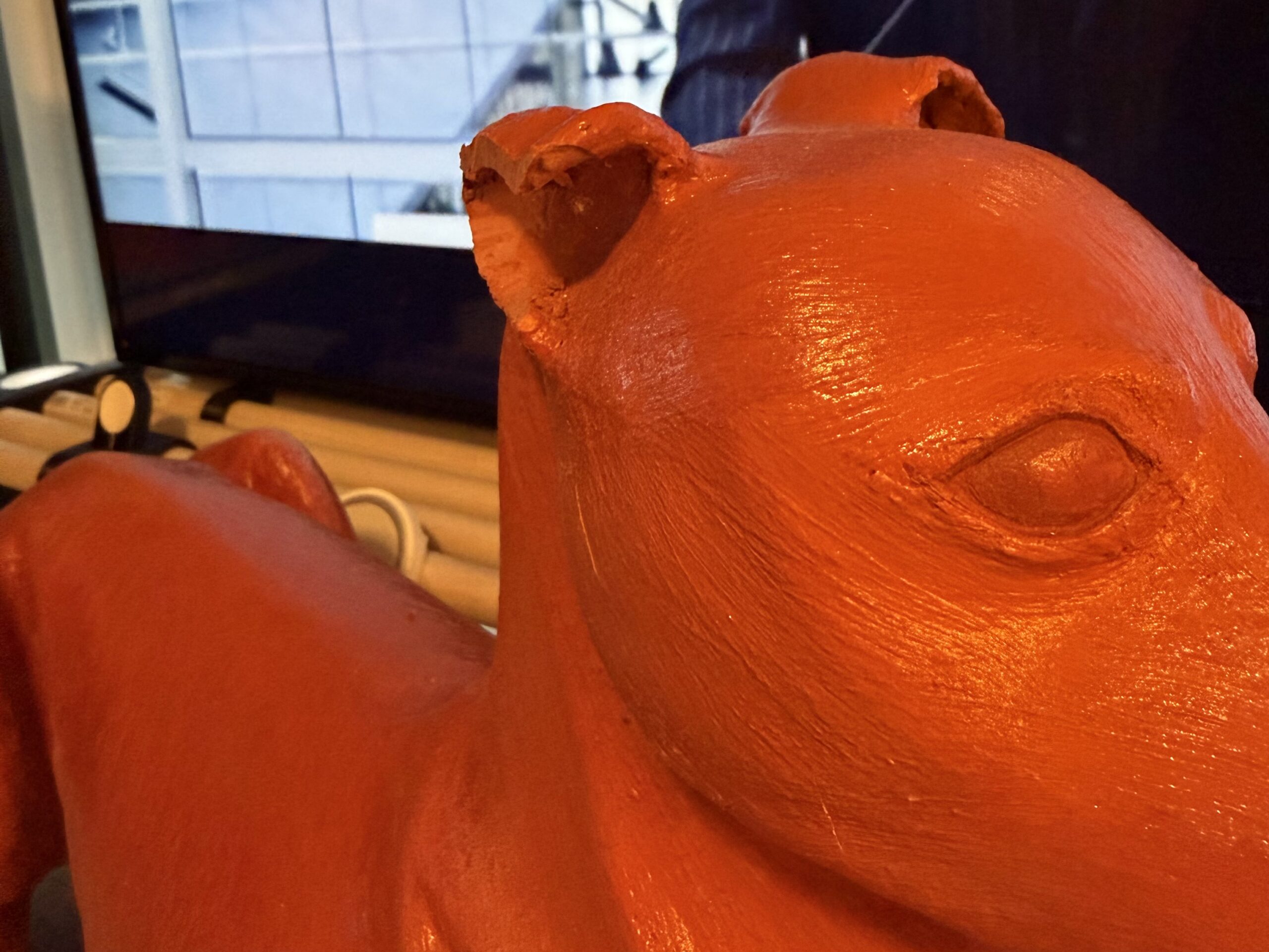
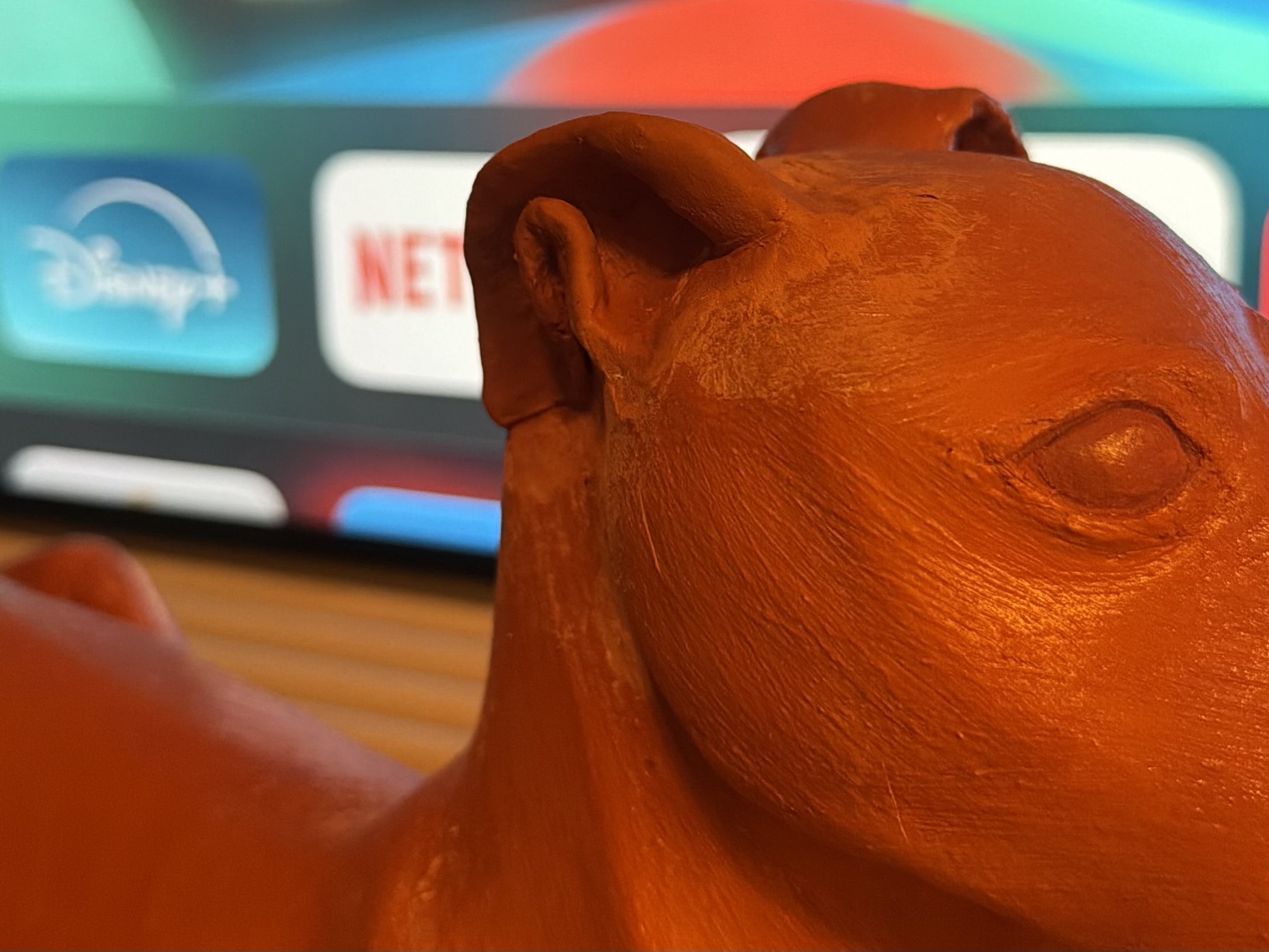
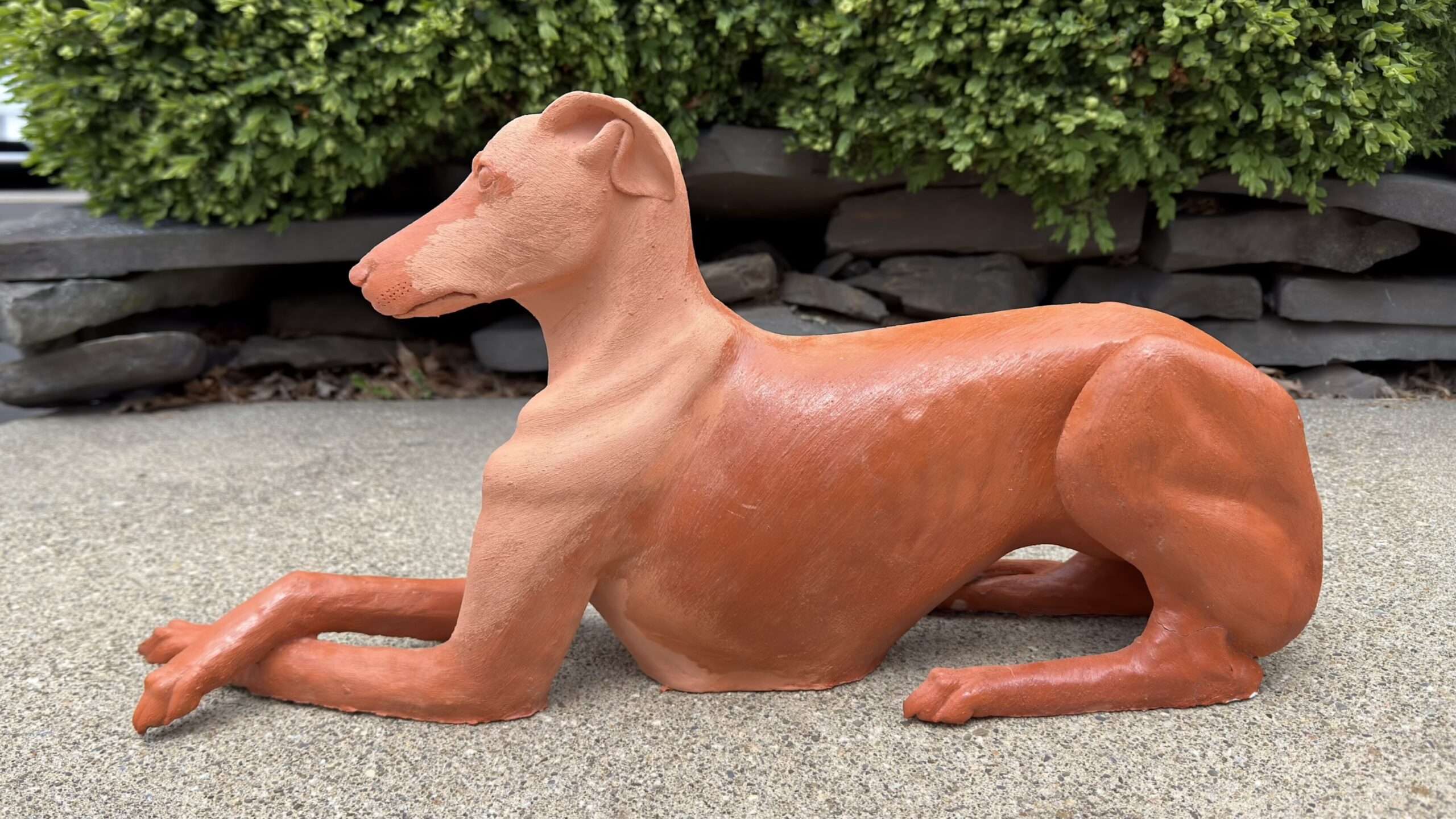
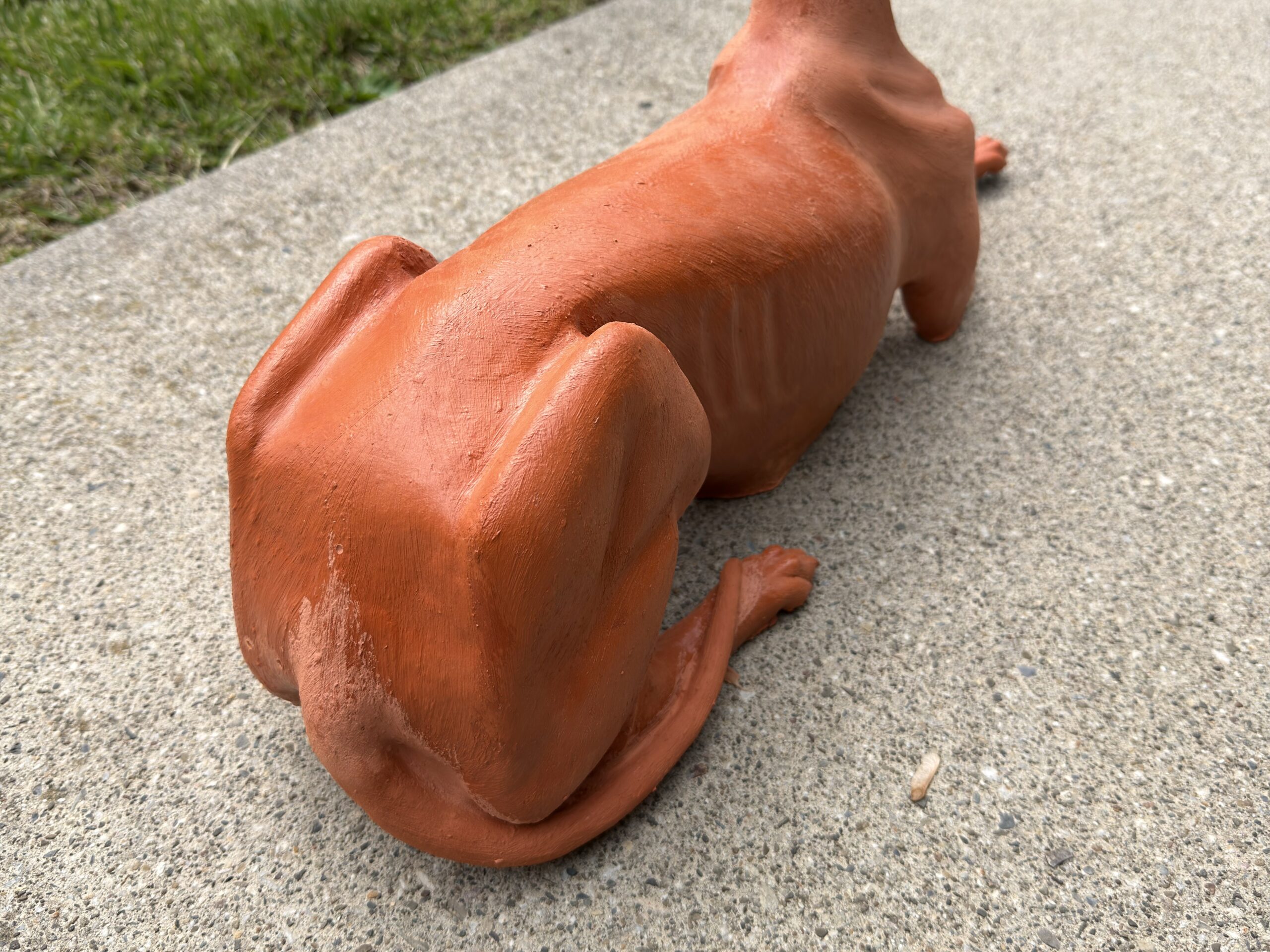
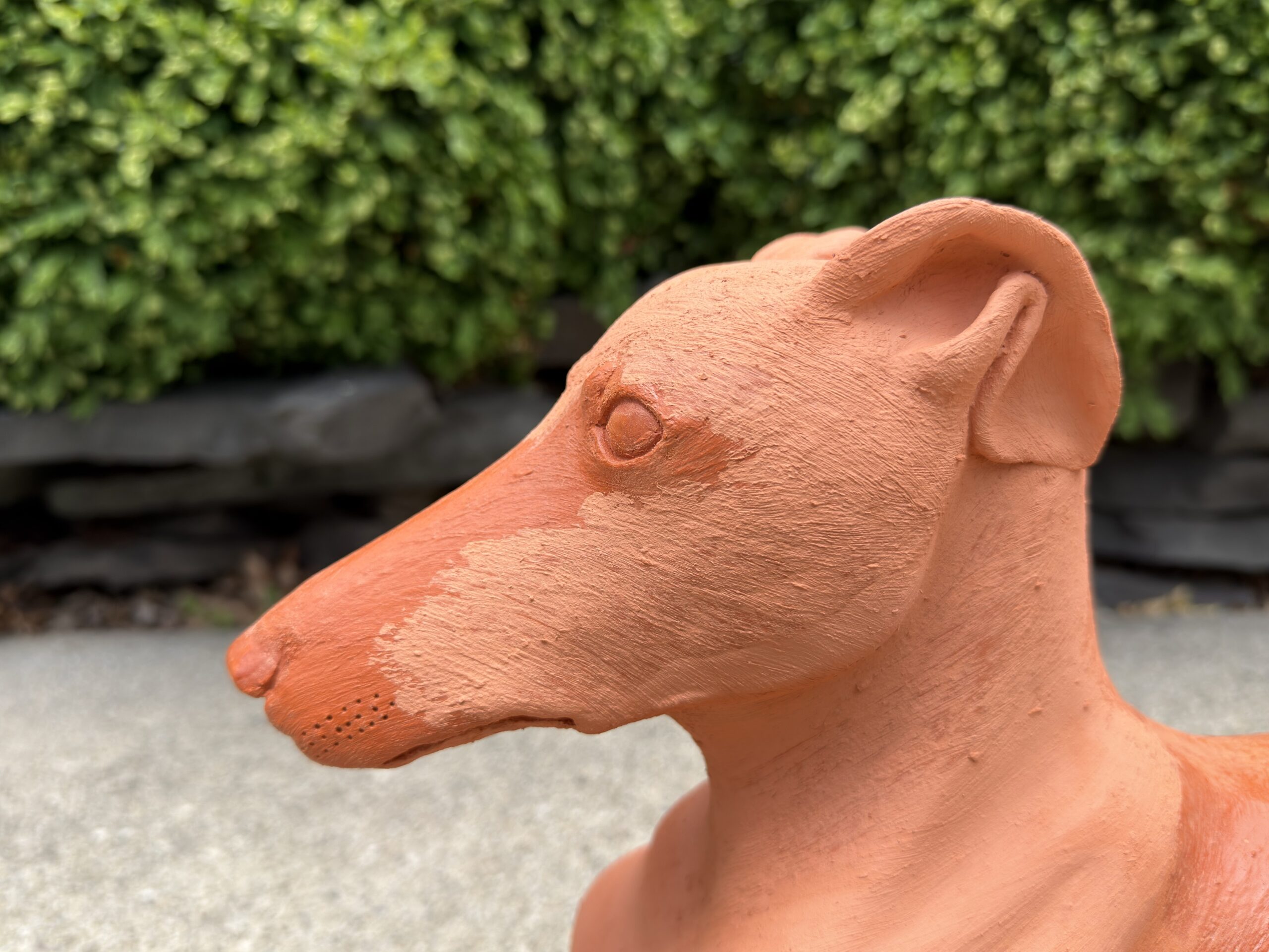
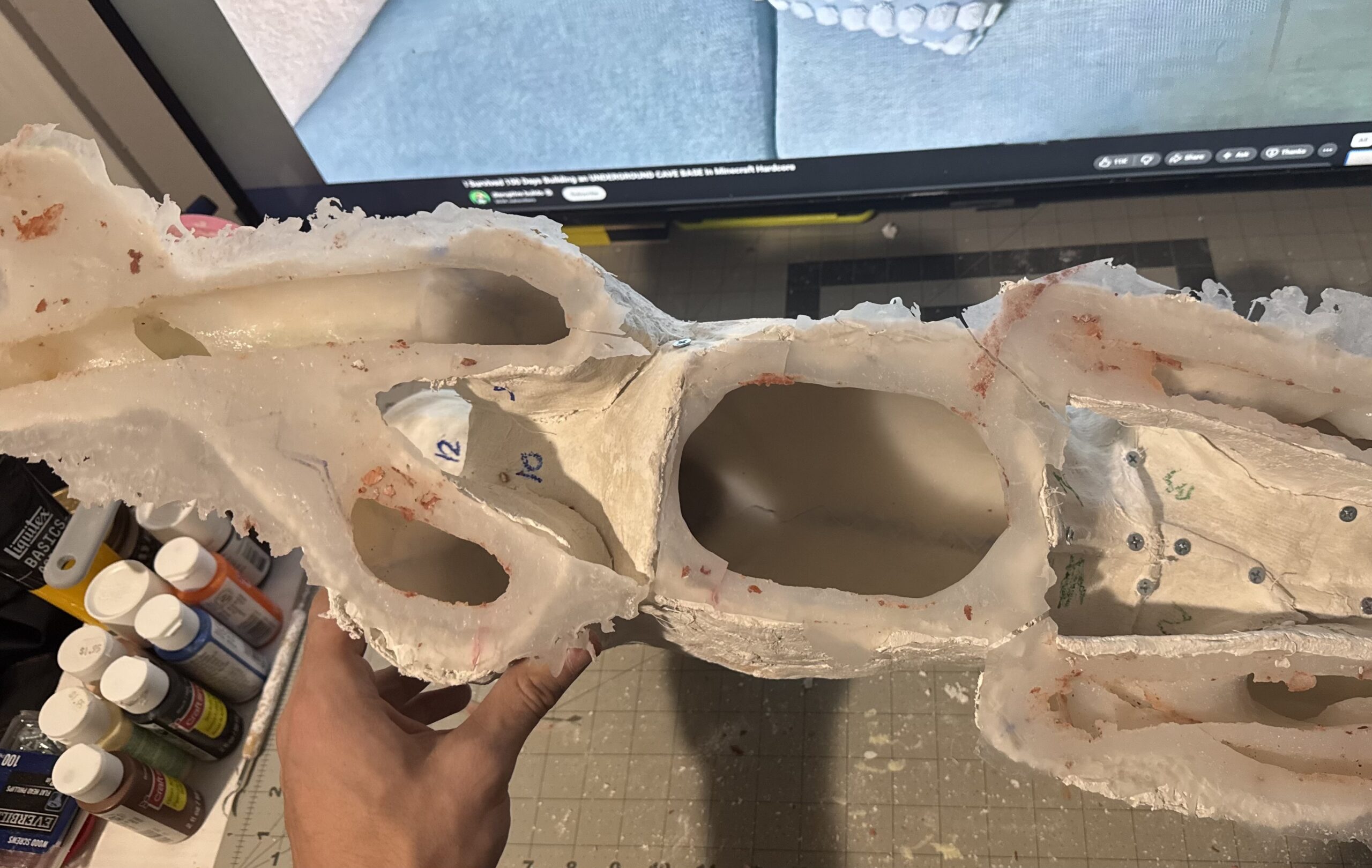
Most of the first silicone stayed. New material only went where the sculpt was remolded. The jacket changed completely. Four casts had already chewed the plaster up when demolding and forced repairs every time, hence a better jacket was needed. Heat shrink ABS replaced it, still in multiple parts, however the flexibility of the plastic allowed for a reduction in the part count. Two casts later the plastic has not needed a repair, and the concrete could be broken off the jacket instead of the jacket breaking with the part.
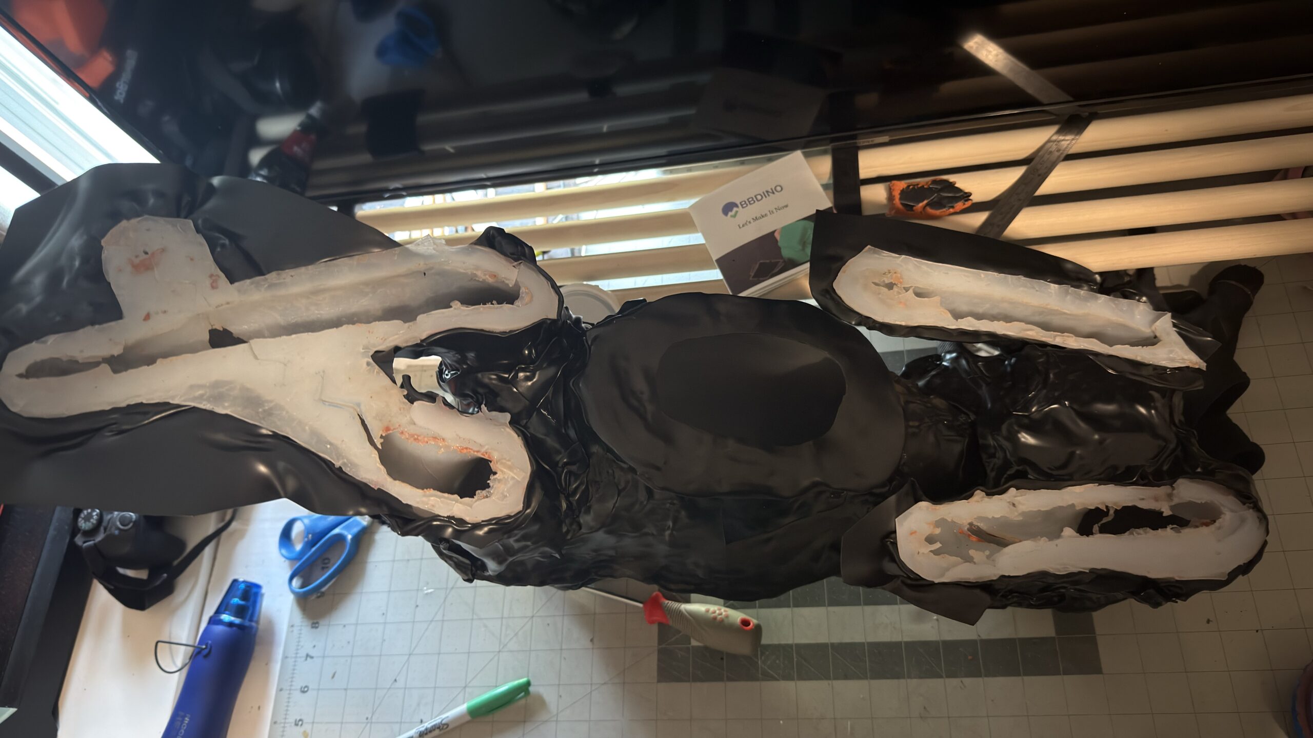
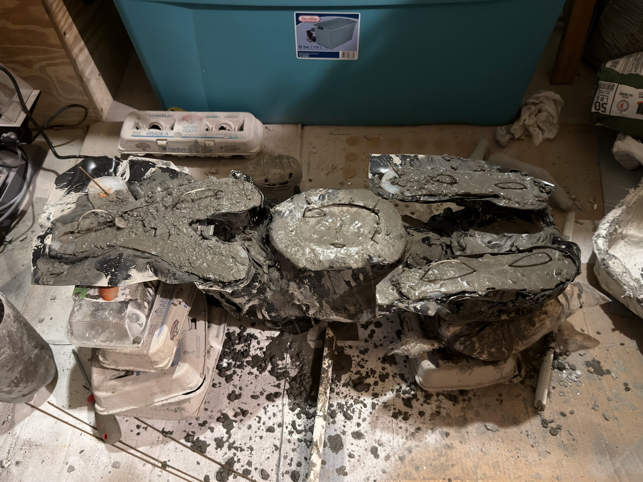
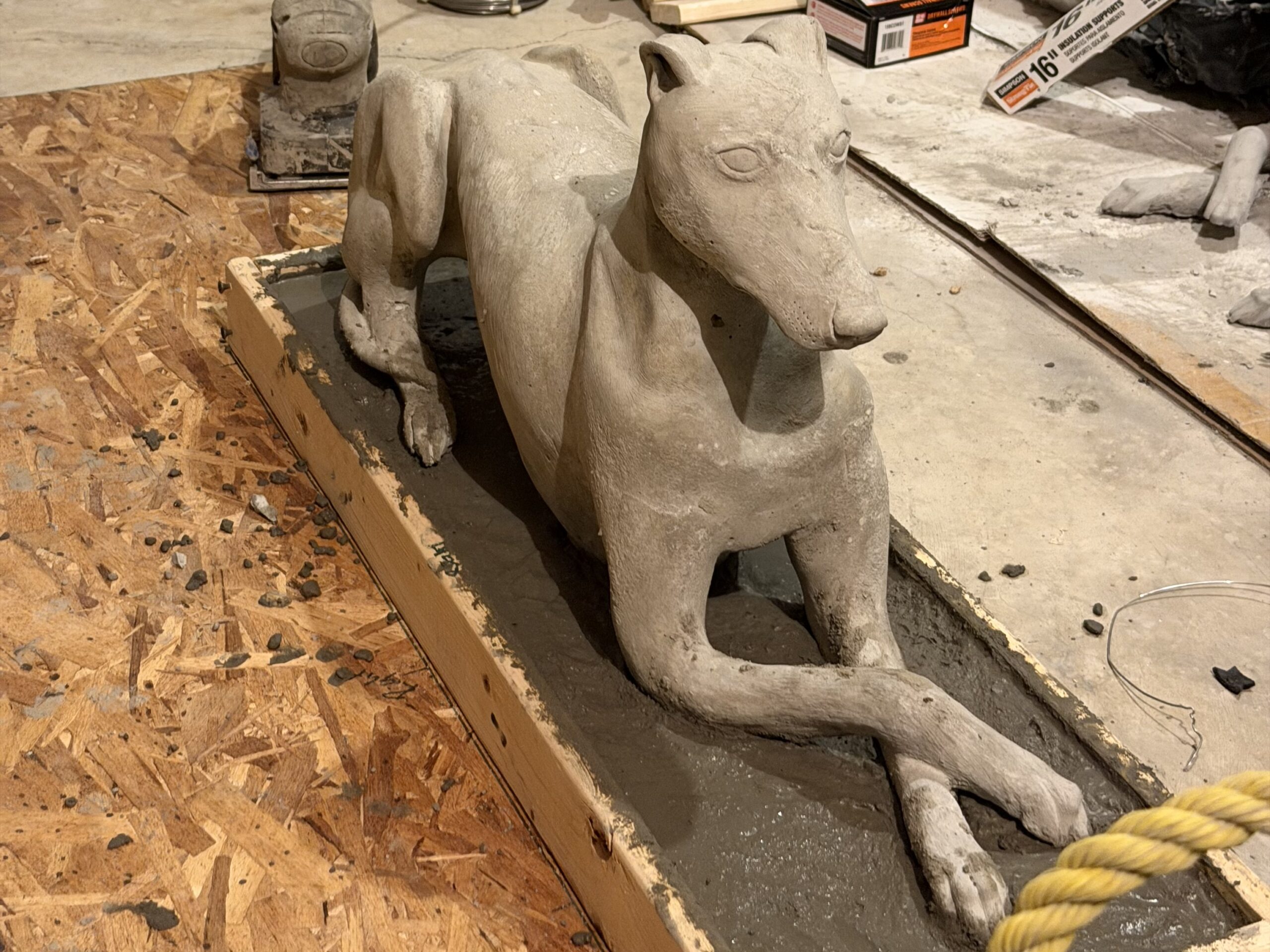
The first ABS pour was a refresher on the revised mold. The second was the one that counted, a dog and a 1.5 in base as one piece. The base mold was wood. Rebar in the pup was bent through the legs and belly so it locked into the slab. After demold any air bubble holes were filled, raised edges sanded, the whole thing sealed, and the concrete spray went back on.
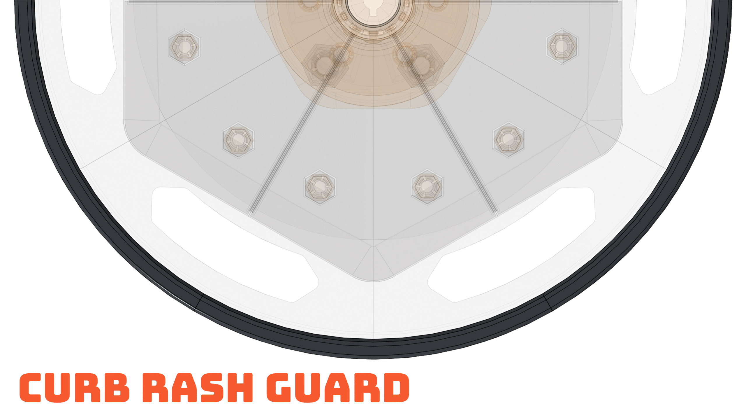
The outer edge of the wheel cover acts as a sacrificial impact zone. Geometry and wall thickness are tuned so the guard deforms and absorbs contact force instead of transferring it into the rim.
The guard is built from independent interlocking segments instead of a continuous ring. Individual segments can be removed and replaced without tools. This supports localized repair and color/finish swaps.

The guard is built from independent interlocking segments instead of a continuous ring. Individual segments can be removed and replaced without tools. This supports localized repair and color/finish swaps.
The interlocking geometry and secondary retention keep remaining segments connected even if one or more are missing or destroyed. The design does not rely on a complete ring for integrity. This is in response to the reality that curb damage is usually localized, keeping the product functional after a curb bump.